(English) Power Manager Deployment Guide
Page 19
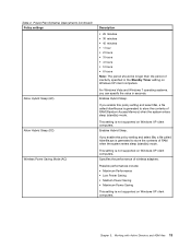
... and select On, a file called hiberfile.sys is not supported on Windows XP client computers. Enables Hybrid Sleep. Specifies the performance of RAM (Random Access Memory) when the system enters sleep (standby) mode. Working with Active Directory and ADM files 13
... and select On, a file called hiberfile.sys is not supported on Windows XP client computers. Enables Hybrid Sleep. Specifies the performance of RAM (Random Access Memory) when the system enters sleep (standby) mode. Working with Active Directory and ADM files 13
BIOS Windows Management Instrumentation Interface Deployment Guide
Page 15
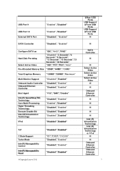
...Seconds", "12 Seconds","15 Seconds","21 Seconds","30 Seconds" "IGD","PCI","PEG","Auto" Pre-Allocated Memory Size "32MB","64MB","128MB" Total Graphics Memory "128MB","256MB","Maximum" Multi-Monitor Support Onboard Audio Controller Onboard Ethernet Controller "Disabled","Enabled" "...Enabled" "Disabled","Enabled" VT-d "Disabled","Enabled" TxT C State Support Turbo Mode Intel(R) Manageability Control Intel(R) Manageability Reset @Copyright Lenovo 2011 "Disabled","Enabled" "C1","C1C3","C1C3C6" "Disabled","Enabled" "Disabled","Enabled" "Disabled","Enabled" &Rear USB Ports USB Support ...
...Seconds", "12 Seconds","15 Seconds","21 Seconds","30 Seconds" "IGD","PCI","PEG","Auto" Pre-Allocated Memory Size "32MB","64MB","128MB" Total Graphics Memory "128MB","256MB","Maximum" Multi-Monitor Support Onboard Audio Controller Onboard Ethernet Controller "Disabled","Enabled" "...Enabled" "Disabled","Enabled" VT-d "Disabled","Enabled" TxT C State Support Turbo Mode Intel(R) Manageability Control Intel(R) Manageability Reset @Copyright Lenovo 2011 "Disabled","Enabled" "C1","C1C3","C1C3C6" "Disabled","Enabled" "Disabled","Enabled" "Disabled","Enabled" &Rear USB Ports USB Support ...
Hardware Maintenance Manual
Page 3
... the computer cover 79 Removing and reinstalling the front bezel . . 80 Installing or replacing a PCI card 81 Installing or replacing a memory module . . . 84 Installing or replacing the optical drive . . . 86 Installing or replacing the card reader . . ....92 Replacing the power supply assembly . . . 93 Replacing the heat sink and fan assembly . . 95 Replacing the microprocessor 97 © Copyright Lenovo 2011, 2012 i Contents Chapter 1. Safety information 3 General safety 3 Electrical safety 3 Voltage-selection switch 5 Safety inspection guide 5 Handling electrostatic discharge-...
... the computer cover 79 Removing and reinstalling the front bezel . . 80 Installing or replacing a PCI card 81 Installing or replacing a memory module . . . 84 Installing or replacing the optical drive . . . 86 Installing or replacing the card reader . . ....92 Replacing the power supply assembly . . . 93 Replacing the heat sink and fan assembly . . 95 Replacing the microprocessor 97 © Copyright Lenovo 2011, 2012 i Contents Chapter 1. Safety information 3 General safety 3 Electrical safety 3 Voltage-selection switch 5 Safety inspection guide 5 Handling electrostatic discharge-...
Hardware Maintenance Manual
Page 4
... the computer cover 121 Removing and reinstalling the front bezel . . 122 Accessing the system board components and drives 124 Installing or replacing a memory module . . . 125 Installing or replacing a PCI card 126 Installing or replacing the card reader . . . . 128 Replacing the ... 5049, 5070, and 7518 163 Mechanical FRUs 178 Keyboard and Mouse 185 Adapters and miscellaneous FRUs 228 Power Cords 232 Recovery discs 241 ii ThinkCentre Hardware Maintenance Manual Windows 7 Home Premium 32 Recovery CD 241 Windows 7 Professional 32 Recovery CD . . 244 Windows 7 Professional 64 Recovery...
... the computer cover 121 Removing and reinstalling the front bezel . . 122 Accessing the system board components and drives 124 Installing or replacing a memory module . . . 125 Installing or replacing a PCI card 126 Installing or replacing the card reader . . . . 128 Replacing the ... 5049, 5070, and 7518 163 Mechanical FRUs 178 Keyboard and Mouse 185 Adapters and miscellaneous FRUs 228 Power Cords 232 Recovery discs 241 ii ThinkCentre Hardware Maintenance Manual Windows 7 Home Premium 32 Recovery CD 241 Windows 7 Professional 32 Recovery CD . . 244 Windows 7 Professional 64 Recovery...

Hardware Maintenance Manual
Page 49
...you hear multiple beeps or see "Using passwords" on the screen. Note: After you can use your computer, regardless of the following sections. © Copyright Lenovo 2011, 2012 43 Then, follow the instructions on page 43. You can set any passwords, read the following : • Press F1 to perform various ... the F1 key when turning on page 43. When the POST detects that the hard disk drive has been removed from your computer or the memory module size has decreased, an error message will not be displayed again. • Press F2 to your computer is used to enter the Setup...
...you hear multiple beeps or see "Using passwords" on the screen. Note: After you can use your computer, regardless of the following sections. © Copyright Lenovo 2011, 2012 43 Then, follow the instructions on page 43. You can set any passwords, read the following : • Press F1 to perform various ... the F1 key when turning on page 43. When the POST detects that the hard disk drive has been removed from your computer or the memory module size has decreased, an error message will not be displayed again. • Press F2 to your computer is used to enter the Setup...

Hardware Maintenance Manual
Page 56
... board 1. Adapter card 3. System board 1. Re-start the test, if necessary 1. Flash the system. System board 1. Reboot the system 2. Run memory test 4. Flash the system. System board 1. Flash the system. System board Information only Re-start the test to review the log file 2. See ..."Updating (flashing) the BIOS from a disc" on page 365. 2. Press F3 to reset the log file 50 ThinkCentre Hardware Maintenance Manual Flash the system. Flash the system. Flash the system. In the following index, X can represent any number. Flash ...
... board 1. Adapter card 3. System board 1. Re-start the test, if necessary 1. Flash the system. System board 1. Reboot the system 2. Run memory test 4. Flash the system. System board 1. Flash the system. System board Information only Re-start the test to review the log file 2. See ..."Updating (flashing) the BIOS from a disc" on page 365. 2. Press F3 to reset the log file 50 ThinkCentre Hardware Maintenance Manual Flash the system. Flash the system. Flash the system. In the following index, X can represent any number. Flash ...

Hardware Maintenance Manual
Page 57
... problems" on page 365 3. See "Updating (flashing) the BIOS from a disc" on page 71 1. See "Updating (flashing) the BIOS from a disc" on page 365 2. Run memory test 4. Diagnostic Error Code 000-197-XXX BIOS test warning 000-198-XXX BIOS test aborted 000-199-XXX BIOS test failed, cause unknown 000...
... problems" on page 365 3. See "Updating (flashing) the BIOS from a disc" on page 71 1. See "Updating (flashing) the BIOS from a disc" on page 365 2. Run memory test 4. Diagnostic Error Code 000-197-XXX BIOS test warning 000-198-XXX BIOS test aborted 000-199-XXX BIOS test failed, cause unknown 000...

Hardware Maintenance Manual
Page 63
... a disc" on page 365 3. System board 1. System board System board 1. If a component is called out in warning statement 4. Remove USB device(s) and re-test 2. Run memory test 4. Symptom-to "Undetermined problems" on page 365 3. System board No action 1. Flash the system and re-test. System board System board 1. See "Updating (flashing...
... a disc" on page 365 3. System board 1. System board System board 1. If a component is called out in warning statement 4. Remove USB device(s) and re-test 2. Run memory test 4. Symptom-to "Undetermined problems" on page 365 3. System board No action 1. Flash the system and re-test. System board System board 1. See "Updating (flashing...

Hardware Maintenance Manual
Page 71
... error 185-000-XXX Asset Security Test Passed 185-XXX-XXX Asset Security failure 185-278-XXX Asset Security Chassis Intrusion 201-000-XXX System Memory Test Passed FRU/Action 1. System board No action 1. Press F3 to reset the log file 1. Make sure the component that is called out in warning...
... error 185-000-XXX Asset Security Test Passed 185-XXX-XXX Asset Security failure 185-278-XXX Asset Security Chassis Intrusion 201-000-XXX System Memory Test Passed FRU/Action 1. System board No action 1. Press F3 to reset the log file 1. Make sure the component that is called out in warning...

Hardware Maintenance Manual
Page 72
... Drive and re-test the system 1. System board No action Remove the Joystick and re-test the system 66 ThinkCentre Hardware Maintenance Manual Diagnostic Error Code 201-XXX-XXX System Memory error 202-000-XXX System Cache Test Passed 202-XXX-XXX System Cache error 206-000-XXX Diskette Drive Test...-000-XXX Mouse Test Passed 302-XXX-XXX Mouse error 303-000-XXX Joystick Test Passed 303-XXX-XXX Joystick error FRU/Action 1. Replace the memory module called out by the test 2. Check power supply voltages 3. CD-ROM drive 4. Hard Disk Drive Cable 2. System board No action 1. Keyboard 2. Check ...
... Drive and re-test the system 1. System board No action Remove the Joystick and re-test the system 66 ThinkCentre Hardware Maintenance Manual Diagnostic Error Code 201-XXX-XXX System Memory error 202-000-XXX System Cache Test Passed 202-XXX-XXX System Cache error 206-000-XXX Diskette Drive Test...-000-XXX Mouse Test Passed 302-XXX-XXX Mouse error 303-000-XXX Joystick Test Passed 303-XXX-XXX Joystick error FRU/Action 1. Replace the memory module called out by the test 2. Check power supply voltages 3. CD-ROM drive 4. Hard Disk Drive Cable 2. System board No action 1. Keyboard 2. Check ...

Hardware Maintenance Manual
Page 73
...setting error 1 long and 2 short beeps Monitor or video adapter card error 1 long and 9 short beeps BIOS ROM error Continuous long beeps DRAM memory error FRU/Action Perform the following actions in order. 1. Perform a Boot-block recovery. Replace the system board. Perform the following actions in order....-250-XXX Monitor DDC self test failure 415-000-XXXModem Test Passed 415-XXX-XXX Modem error FRU/Action No action 1. Make sure the memory module(s) are tones or a series of tones separated by pauses (intervals without sound) during POST. See "Recovering from a POST and BIOS...
...setting error 1 long and 2 short beeps Monitor or video adapter card error 1 long and 9 short beeps BIOS ROM error Continuous long beeps DRAM memory error FRU/Action Perform the following actions in order. 1. Perform a Boot-block recovery. Replace the system board. Perform the following actions in order....-250-XXX Monitor DDC self test failure 415-000-XXXModem Test Passed 415-XXX-XXX Modem error FRU/Action No action 1. Make sure the memory module(s) are tones or a series of tones separated by pauses (intervals without sound) during POST. See "Recovering from a POST and BIOS...

Hardware Maintenance Manual
Page 74
... or no longer functional. This information gives specifics about the type and location of tests that the boot drive is no keyboard present Memory Test: Memory test fail Description/Action The CMOS battery is working If the POST detects a problem, an error message appears on the system. Checksum... error messages probably will not appear on the screen the next time you power-on the system, it performs a series of the memory error. 68 ThinkCentre Hardware Maintenance Manual defaults loaded CPU at nnnn Press Esc to NONE. Replace the battery. Cannot initialize the keyboard.
... or no longer functional. This information gives specifics about the type and location of tests that the boot drive is no keyboard present Memory Test: Memory test fail Description/Action The CMOS battery is working If the POST detects a problem, an error message appears on the system. Checksum... error messages probably will not appear on the screen the next time you power-on the system, it performs a series of the memory error. 68 ThinkCentre Hardware Maintenance Manual defaults loaded CPU at nnnn Press Esc to NONE. Replace the battery. Cannot initialize the keyboard.

Hardware Maintenance Manual
Page 75
... first device or first device after diskette 2. Check power supply and signal cable connections to the computer. Diskette Drive 2. System Board 3. Memory Module 3. System Board Chapter 7. See "Hard disk drive boot error" on page 49. 1. System Board 3. Ensure network administrator is ... network administrator of new MAC address) Computer will not perform a Wake on LAN 3. Power Supply 2. Hard Disk Drive Cable Incorrect memory size during POST 1. Make sure the boot drive is enabled for RPL 3. Power Switch 2. Ensure that network adapter is properly connected...
... first device or first device after diskette 2. Check power supply and signal cable connections to the computer. Diskette Drive 2. System Board 3. Memory Module 3. System Board Chapter 7. See "Hard disk drive boot error" on page 49. 1. System Board 3. Ensure network administrator is ... network administrator of new MAC address) Computer will not perform a Wake on LAN 3. Power Supply 2. Hard Disk Drive Cable Incorrect memory size during POST 1. Make sure the boot drive is enabled for RPL 3. Power Switch 2. Ensure that network adapter is properly connected...

Hardware Maintenance Manual
Page 77
..." on page 100 or "Replacing the system board" on the power and the computer to -FRU index 71 Symptom-to re-test the system. 4. Memory modules d. Extended video memory e. Turn on page 150. Diskette drive 3. External Cache f. Turn off the computer and the power. 2. Repeat steps 1 through 3 until you encounter undetermined problems...
..." on page 100 or "Replacing the system board" on the power and the computer to -FRU index 71 Symptom-to re-test the system. 4. Memory modules d. Extended video memory e. Turn on page 150. Diskette drive 3. External Cache f. Turn off the computer and the power. 2. Repeat steps 1 through 3 until you encounter undetermined problems...

Hardware Maintenance Manual
Page 82
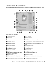
Locating components Figure 3 "Component locations" on page 79. Component locations 1 Heat sink and fan assembly 2 Microprocessor 3 Memory modules 4 Optical drive 5 Front audio and USB assembly 6 Internal speaker (installed in some models) 7 Hard disk drive 8 PCI card (installed in your computer. Figure 3. To ... the various components in some models) 9 System board 10 Cover presence switch (also called intrusion switch) 11 Rear fan assembly 12 Power supply assembly 76 ThinkCentre Hardware Maintenance Manual
Locating components Figure 3 "Component locations" on page 79. Component locations 1 Heat sink and fan assembly 2 Microprocessor 3 Memory modules 4 Optical drive 5 Front audio and USB assembly 6 Internal speaker (installed in some models) 7 Hard disk drive 8 PCI card (installed in your computer. Figure 3. To ... the various components in some models) 9 System board 10 Cover presence switch (also called intrusion switch) 11 Rear fan assembly 12 Power supply assembly 76 ThinkCentre Hardware Maintenance Manual
Hardware Maintenance Manual
Page 83
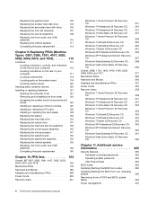
...15 eSATA connector 2 Microprocessor 16 Power fan connector 3 Microprocessor fan connector 17 Front panel connector (for connecting LED indicators and power switch) 4 Memory slot 1 (DIMM1) 18 Front USB connector 1 (for connecting USB ports 1 and 2 on the system board. Replacing FRUs (Machine Types:...page 77 shows the locations of the parts on the front bezel) 5 Memory slot 2 (DIMM2) 19 Front USB connector 2 (for connecting additional USB devices) 6 Memory slot 3 (DIMM3) 20 Serial (COM2) connector 7 Memory slot 4 (DIMM4) 21 Internal speaker connector 8 Thermal sensor connector 22 ...
...15 eSATA connector 2 Microprocessor 16 Power fan connector 3 Microprocessor fan connector 17 Front panel connector (for connecting LED indicators and power switch) 4 Memory slot 1 (DIMM1) 18 Front USB connector 1 (for connecting USB ports 1 and 2 on the system board. Replacing FRUs (Machine Types:...page 77 shows the locations of the parts on the front bezel) 5 Memory slot 2 (DIMM2) 19 Front USB connector 2 (for connecting additional USB devices) 6 Memory slot 3 (DIMM3) 20 Serial (COM2) connector 7 Memory slot 4 (DIMM4) 21 Internal speaker connector 8 Thermal sensor connector 22 ...
Hardware Maintenance Manual
Page 85
Handle PCI cards, memory modules, system boards, and microprocessors by installing or replacing hardware. You can cause static electricity to avoid static-electricity damage: • Limit your specific situation, ... to build up around you. • Always carefully handle the parts and other computer components. Movement can expand the capabilities of the ThinkCentre User Guide, go to: http://www.lenovo.com/ThinkCentreUserGuides This section provides instructions on how to a metal expansion-slot cover or other unpainted metal surface on the computer cover...
Handle PCI cards, memory modules, system boards, and microprocessors by installing or replacing hardware. You can cause static electricity to avoid static-electricity damage: • Limit your specific situation, ... to build up around you. • Always carefully handle the parts and other computer components. Movement can expand the capabilities of the ThinkCentre User Guide, go to: http://www.lenovo.com/ThinkCentreUserGuides This section provides instructions on how to a metal expansion-slot cover or other unpainted metal surface on the computer cover...
Hardware Maintenance Manual
Page 89
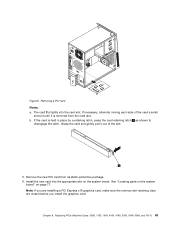
... of the slot. 5. Remove the new PCI card from the card slot. Note: If you are installing a PCI Express x16 graphics card, make sure the memory slot retaining clips are closed before you install the graphics card. Removing a PCI card Notes: a. b. See "Locating parts on the system board" on the system...
... of the slot. 5. Remove the new PCI card from the card slot. Note: If you are installing a PCI Express x16 graphics card, make sure the memory slot retaining clips are closed before you install the graphics card. Removing a PCI card Notes: a. b. See "Locating parts on the system board" on the system...

Hardware Maintenance Manual
Page 90
...to "Completing the parts replacement" on page 113. Figure 10. To complete the installation or replacement, go to: http://www.lenovo.com/ThinkCentreUserGuides This section provides instructions on page 79. 3. Your computer has four slots for installing or replacing DDR3 UDIMMs that ... Guide. Remove the computer cover. Lay the computer on your computer model, you are installing or replacing a memory module, do the following : 84 ThinkCentre Hardware Maintenance Manual Locate the memory slots. See "Installing or replacing a PCI card" on page 77. See "Locating parts on the system board...
...to "Completing the parts replacement" on page 113. Figure 10. To complete the installation or replacement, go to: http://www.lenovo.com/ThinkCentreUserGuides This section provides instructions on page 79. 3. Your computer has four slots for installing or replacing DDR3 UDIMMs that ... Guide. Remove the computer cover. Lay the computer on your computer model, you are installing or replacing a memory module, do the following : 84 ThinkCentre Hardware Maintenance Manual Locate the memory slots. See "Installing or replacing a PCI card" on page 77. See "Locating parts on the system board...
Hardware Maintenance Manual
Page 91
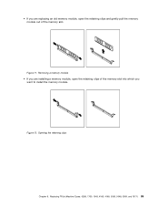
Opening the retaining clips Chapter 8. Figure 11. • If you are installing a memory module, open the retaining clips and gently pull the memory module out of the memory slot into which you are replacing an old memory module, open the retaining clips of the memory slot. Removing a memory module • If you want to install the memory module. Replacing FRUs (Machine Types: 0268, 1730, 1943, 4166, 4169, 5030, 5048, 5069, and 7517) 85 Figure 12.
Opening the retaining clips Chapter 8. Figure 11. • If you are installing a memory module, open the retaining clips and gently pull the memory module out of the memory slot into which you are replacing an old memory module, open the retaining clips of the memory slot. Removing a memory module • If you want to install the memory module. Replacing FRUs (Machine Types: 0268, 1730, 1943, 4166, 4169, 5030, 5048, 5069, and 7517) 85 Figure 12.


