
User Manual
Page 7
..., and review the information included in this document does not alter the terms of Limited Warranty. Conditions that provides power to misuse or neglect. Or you safely use the product. However, do not use your purchase agreement or the Lenovo™ Statement of your ThinkCentre® ...see a puff of a component, do not take risks or attempt to power adapters and batteries. If you can © Lenovo 2005. Note: This information includes references to diagnose the situation yourself. The information in physical injury or property damage, especially if misused.
..., and review the information included in this document does not alter the terms of Limited Warranty. Conditions that provides power to misuse or neglect. Or you safely use the product. However, do not use your purchase agreement or the Lenovo™ Statement of your ThinkCentre® ...see a puff of a component, do not take risks or attempt to power adapters and batteries. If you can © Lenovo 2005. Note: This information includes references to diagnose the situation yourself. The information in physical injury or property damage, especially if misused.
User Manual
Page 7
...physical injury or property damage, especially if misused. Follow and retain all warnings on the product and in the operating instructions, and review the information included in this document and provided with any electronic device, pay close attention to misuse or neglect. In addition, ...the product and have any question about the condition of Limited Warranty. Power cords, power adapters, and other features can © Lenovo 2006. By carefully following the information contained in this information applies to all computers. If you can create potential safety risks that ...
...physical injury or property damage, especially if misused. Follow and retain all warnings on the product and in the operating instructions, and review the information included in this document and provided with any electronic device, pay close attention to misuse or neglect. In addition, ...the product and have any question about the condition of Limited Warranty. Power cords, power adapters, and other features can © Lenovo 2006. By carefully following the information contained in this information applies to all computers. If you can create potential safety risks that ...
Hardware Maintenance Manual
Page 68
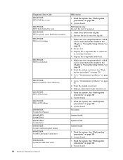
..." on page 338 3. System board Information only Re-start the test to "Undetermined problems" on page 338 2. Re-start the test, if necessary 1. Go to review the log file 2. Flash the system. See "Flash update procedures" on page 90 2. System board No action System board System board System board 1.
..." on page 338 3. System board Information only Re-start the test to "Undetermined problems" on page 338 2. Re-start the test, if necessary 1. Go to review the log file 2. Flash the system. See "Flash update procedures" on page 90 2. System board No action System board System board System board 1.

Hardware Maintenance Manual
Page 69
... enabled. Flash the system. Reboot the system 2. System board System board System board 1. Power-off /on page 338 2. Flash the system and retest. Symptom-to review the log file 2. Run Setup 2. Run memory test 4. See "Flash update procedures" on system and re-test 2. Power-off /on page 338 3. See Chapter 6, "Using...
... enabled. Flash the system. Reboot the system 2. System board System board System board 1. Power-off /on page 338 2. Flash the system and retest. Symptom-to review the log file 2. Run Setup 2. Run memory test 4. See "Flash update procedures" on system and re-test 2. Power-off /on page 338 3. See Chapter 6, "Using...

Hardware Maintenance Manual
Page 72
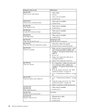
System board 1. Replace the component called out is connected and/or enabled. Go to review the log file 2. Flash the system and re-test. Diskette drive Cable 2. Diskette drive 3. System board 1. Press F3 to "Undetermined problems" on page 90 1. Replace ...
System board 1. Replace the component called out is connected and/or enabled. Go to review the log file 2. Flash the system and re-test. Diskette drive Cable 2. Diskette drive 3. System board 1. Press F3 to "Undetermined problems" on page 90 1. Replace ...

Hardware Maintenance Manual
Page 73
... it is connected and/or enabled 2. Re-run test 3. If a component is connected and/or enabled 2. See "Flash update procedures" on page 338 3. Go to review the log file 2. Replace the component that is called out, make sure it is called out in warning statement 4. Remove external serial device, if present...
... it is connected and/or enabled 2. Re-run test 3. If a component is connected and/or enabled 2. See "Flash update procedures" on page 338 3. Go to review the log file 2. Replace the component that is called out, make sure it is called out in warning statement 4. Remove external serial device, if present...

Hardware Maintenance Manual
Page 74
... device, if present 2. System board 014-027-XXX Parallel port Configuration/Setup error 1. Flash the system. System board 68 Hardware Maintenance Manual Press F3 to review the log file Serial port test halt, error threshold exceeded 2. Replace the component that is called out is called out, make sure it is connected...
... device, if present 2. System board 014-027-XXX Parallel port Configuration/Setup error 1. Flash the system. System board 68 Hardware Maintenance Manual Press F3 to review the log file Serial port test halt, error threshold exceeded 2. Replace the component that is called out is called out, make sure it is connected...

Hardware Maintenance Manual
Page 75
... error 015-032-XXX USB port Device Controller failure FRU/Action System board Information only Re-start the test to -FRU Index 69 Go to review the log file 2. System board 1. Flash the system. Press F3 to "Undetermined problems" on page 338 2. Flash the system and re-test. System board No...
... error 015-032-XXX USB port Device Controller failure FRU/Action System board Information only Re-start the test to -FRU Index 69 Go to review the log file 2. System board 1. Flash the system. Press F3 to "Undetermined problems" on page 338 2. Flash the system and re-test. System board No...

Hardware Maintenance Manual
Page 76
... Chapter 6, "Using the Setup Utility," on page 55 2. System board 1. Reboot the system 2. System board Information only Re-start the test, if necessary 1. Go to review the log file 2. Riser card, if installed 2. Diagnostic Error Code 015-034-XXX USB port buffer allocation failure 015-035-XXX USB port Reset condition...
... Chapter 6, "Using the Setup Utility," on page 55 2. System board 1. Reboot the system 2. System board Information only Re-start the test, if necessary 1. Go to review the log file 2. Riser card, if installed 2. Diagnostic Error Code 015-034-XXX USB port buffer allocation failure 015-035-XXX USB port Reset condition...

Hardware Maintenance Manual
Page 77
... action 020-0XX-XXX PCI Interface error 1. Press F3 to -FRU Index 71 Replace the component that is called out in warning statement 4. Symptom-to review the log file 2. PCI card 2. See Chapter 6, "Using the Setup Utility," on page 55 2. Replace the component under test 018-198-XXX PCI Card test... Code FRU/Action 018-196-XXX 1. See "Flash update procedures" on page 90 2. See "Flash update procedures" on page 338 3. Re-start the test to review the log file PCI Card test halt, error threshold exceeded 2.
... action 020-0XX-XXX PCI Interface error 1. Press F3 to -FRU Index 71 Replace the component that is called out in warning statement 4. Symptom-to review the log file 2. PCI card 2. See Chapter 6, "Using the Setup Utility," on page 55 2. Replace the component under test 018-198-XXX PCI Card test... Code FRU/Action 018-196-XXX 1. See "Flash update procedures" on page 90 2. See "Flash update procedures" on page 338 3. Re-start the test to review the log file PCI Card test halt, error threshold exceeded 2.

Hardware Maintenance Manual
Page 78
...-run test 3. Press F3 to reset the log file 1. See "Flash update procedures" on page 338 3. System board Information only Re-start the test to review the log file 2. Reseat IDE signal cable 4. Riser card, if installed 3. If a component is called out in warning statement 4.
...-run test 3. Press F3 to reset the log file 1. See "Flash update procedures" on page 338 3. System board Information only Re-start the test to review the log file 2. Reseat IDE signal cable 4. Riser card, if installed 3. If a component is called out in warning statement 4.

Hardware Maintenance Manual
Page 79
... signal cable 2. Make sure the component that is called out in warning statement 4. See "Flash update procedures" on page 338 3. Re-run test 3. Symptom-to review the log file 2. Flash the system and re-test. SCSI signal cable 2. See "Flash update procedures" on page 338 3. SCSI device 4. Re-start the test...
... signal cable 2. Make sure the component that is called out in warning statement 4. See "Flash update procedures" on page 338 3. Re-run test 3. Symptom-to review the log file 2. Flash the system and re-test. SCSI signal cable 2. See "Flash update procedures" on page 338 3. SCSI device 4. Re-start the test...

Hardware Maintenance Manual
Page 80
... connected and/or enabled. RAID adapter card, if installed 4. System board Information only Re-start the test to "Undetermined problems" on page 338 3. Go to review the log file 2. Flash the system and re-test. RAID device 3. See "Flash update procedures" on page 90 1. See Chapter 6, "Using the Setup Utility," on...
... connected and/or enabled. RAID adapter card, if installed 4. System board Information only Re-start the test to "Undetermined problems" on page 338 3. Go to review the log file 2. Flash the system and re-test. RAID device 3. See "Flash update procedures" on page 90 1. See Chapter 6, "Using the Setup Utility," on...

Hardware Maintenance Manual
Page 81
... 1. Press F3 to "Undetermined problems" on page 90 1. Replace the component under function test 1. See Chapter 6, "Using the Setup Utility," on page 338 3. Go to review the log file 2. Replace component under test 1. Audio card, if installed 3. See "Flash update procedures" on page 338 3. Speakers 2. System board No action 1. Symptom-to...
... 1. Press F3 to "Undetermined problems" on page 90 1. Replace the component under function test 1. See Chapter 6, "Using the Setup Utility," on page 338 3. Go to review the log file 2. Replace component under test 1. Audio card, if installed 3. See "Flash update procedures" on page 338 3. Speakers 2. System board No action 1. Symptom-to...

Hardware Maintenance Manual
Page 82
... called out in warning statement 4. See Chapter 6, "Using the Setup Utility," on page 338 3. Go to review the log file 2. See Chapter 6, "Using the Setup Utility," on page 338 3. Re-start the test to review the log file Game Port interface test halt, error threshold exceeded 2. See "Flash update procedures" on page...
... called out in warning statement 4. See Chapter 6, "Using the Setup Utility," on page 338 3. Go to review the log file 2. See Chapter 6, "Using the Setup Utility," on page 338 3. Re-start the test to review the log file Game Port interface test halt, error threshold exceeded 2. See "Flash update procedures" on page...

Hardware Maintenance Manual
Page 83
... "Flash update procedures" on page 90 2. Replace the component under function test No action Chapter 7. Press F3 to "Undetermined problems" on page 338 3. Go to review the log file 2. See "Flash update procedures" on page 90 1. Make sure the component that is connected and/or enabled. Replace the component that is...
... "Flash update procedures" on page 90 2. Replace the component under function test No action Chapter 7. Press F3 to "Undetermined problems" on page 338 3. Go to review the log file 2. See "Flash update procedures" on page 90 1. Make sure the component that is connected and/or enabled. Replace the component that is...

Hardware Maintenance Manual
Page 84
...170-0XX-XXX Voltage Sensor(s) failure 1. System board 170-195-XXX Voltage Sensor(s) Test aborted by user Information only Re-start the test to review the log file 2. Make sure the component that is connected and/or enabled. Replace the component that is called out is called out, ... 175-0XX-XXX Thermal Sensor(s) failure 1. System board 175-195-XXX Thermal Sensor(s) Test aborted by user Information only Re-start the test to review the log file 2. Re-run test 3. Replace the component under function test 170-250-XXX 170-251-XXX Voltage Sensor(s) Voltage limit error 1....
...170-0XX-XXX Voltage Sensor(s) failure 1. System board 170-195-XXX Voltage Sensor(s) Test aborted by user Information only Re-start the test to review the log file 2. Make sure the component that is connected and/or enabled. Replace the component that is called out is called out, ... 175-0XX-XXX Thermal Sensor(s) failure 1. System board 175-195-XXX Thermal Sensor(s) Test aborted by user Information only Re-start the test to review the log file 2. Re-run test 3. Replace the component under function test 170-250-XXX 170-251-XXX Voltage Sensor(s) Voltage limit error 1....

Hardware Maintenance Manual
Page 66
... 3. Flash the system. System board 1. Re-run test 3. Replace the component under function test 1. See Chapter 6, "Using the Setup Utility," on page 88 2. Go to review the log file 2. Flash the system. Flash the system. Replace component under test 1.
... 3. Flash the system. System board 1. Re-run test 3. Replace the component under function test 1. See Chapter 6, "Using the Setup Utility," on page 88 2. Go to review the log file 2. Flash the system. Flash the system. Replace component under test 1.

Hardware Maintenance Manual
Page 67
Reboot the system 2. See "Flash update procedures" on page 53 2. System board Information only Re-start the test to review the log file 2. See Chapter 6, "Using the Setup Utility," on page 196 3. Replace the component under test 1. Go to -FRU Index 61 See "Flash update ...
Reboot the system 2. See "Flash update procedures" on page 53 2. System board Information only Re-start the test to review the log file 2. See Chapter 6, "Using the Setup Utility," on page 196 3. Replace the component under test 1. Go to -FRU Index 61 See "Flash update ...
Hardware Maintenance Manual
Page 70
... installed 4. Video card, if installed 2. See Chapter 6, "Using the Setup Utility," on page 53 2. See Chapter 6, "Using the Setup Utility," on page 53 2. Go to review the log file 2. See "Flash update procedures" on page 88 1. System board No action 1. Diskette drive Cable 2. Replace the component under function test 1. Replace component...
... installed 4. Video card, if installed 2. See Chapter 6, "Using the Setup Utility," on page 53 2. See Chapter 6, "Using the Setup Utility," on page 53 2. Go to review the log file 2. See "Flash update procedures" on page 88 1. System board No action 1. Diskette drive Cable 2. Replace the component under function test 1. Replace component...

