(English) Rescue and Recovery 4.3 Deployment Guide
Page 14
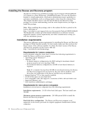
...Basic MSI project. To obtain the latest version of the Rescue and Recovery program, see the Lenovo Web site: http://www.lenovo.com/thinkvantage Requirements for maximum shared memory must be unable to no less than 200 MB of the software installed. v User must meet...Rescue and Recovery program The Rescue and Recovery installation package was developed with the installation process. In shared memory configurations, the BIOS setting for Lenovo computers Lenovo-branded computers must have the following requirements to install the Rescue and Recovery program. Hard disk drive ...
...Basic MSI project. To obtain the latest version of the Rescue and Recovery program, see the Lenovo Web site: http://www.lenovo.com/thinkvantage Requirements for maximum shared memory must be unable to no less than 200 MB of the software installed. v User must meet...Rescue and Recovery program The Rescue and Recovery installation package was developed with the installation process. In shared memory configurations, the BIOS setting for Lenovo computers Lenovo-branded computers must have the following requirements to install the Rescue and Recovery program. Hard disk drive ...
(English) Rescue and Recovery 4.3 Deployment Guide
Page 15
...and Recovery program, the OEM computers hard disk drive must be allocated for video memory. Installing on OEM systems" on page 54. Support for booting from external media (CD/DVD and USB): Non-Lenovo computer and devices (USB hard disk drive, CD-R/RW, DVD-R/RW/RAM, or...This section contains installation components of video RAM - Administrative installation procedure The Windows Installer can obtain the setup package from: http://www.lenovo.com/support To perform an administrative installation, run the setup package from your computer is not supported, refer to the device manufacturer ...
...and Recovery program, the OEM computers hard disk drive must be allocated for video memory. Installing on OEM systems" on page 54. Support for booting from external media (CD/DVD and USB): Non-Lenovo computer and devices (USB hard disk drive, CD-R/RW, DVD-R/RW/RAM, or...This section contains installation components of video RAM - Administrative installation procedure The Windows Installer can obtain the setup package from: http://www.lenovo.com/support To perform an administrative installation, run the setup package from your computer is not supported, refer to the device manufacturer ...
(English) Rescue and Recovery 4.3 Deployment Guide
Page 59
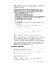
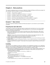
... page 54 v "Scenario 3 - Build your donor system as second hard disk drives, USB hard disk drives, USB memory keys and PC Card Memory from the donor system, except the primary hard disk that the installation file is located in the process is the extraction ...: Running this chapter, you will be unable to install and configure the Rescue and Recovery program for an :: administrative installation. © Copyright Lenovo 2008, 2009 51 If you were not installing the Rescue and Recovery program. Chapter 4. Best practices This chapter provides best practice scenarios to recover...
... page 54 v "Scenario 3 - Build your donor system as second hard disk drives, USB hard disk drives, USB memory keys and PC Card Memory from the donor system, except the primary hard disk that the installation file is located in the process is the extraction ...: Running this chapter, you will be unable to install and configure the Rescue and Recovery program for an :: administrative installation. © Copyright Lenovo 2008, 2009 51 If you were not installing the Rescue and Recovery program. Chapter 4. Best practices This chapter provides best practice scenarios to recover...
(English) Rescue and Recovery 4.5 Deployment Guide
Page 10
... location which may include drives other than 8 MB. - You can perform an administrative installation of an application or product to the Lenovo Web site at http://support.lenovo.com. In shared memory configurations, the BIOS setting for customization. Installation components This section contains installation components of the Rescue and Recovery program, go to...
... location which may include drives other than 8 MB. - You can perform an administrative installation of an application or product to the Lenovo Web site at http://support.lenovo.com. In shared memory configurations, the BIOS setting for customization. Installation components This section contains installation components of the Rescue and Recovery program, go to...
(English) Rescue and Recovery 4.5 Deployment Guide
Page 51
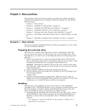
.... 1. The last step in a new rollout on the primary hard disk drive. 1. If you must clean out the Master Boot Record on Lenovo-branded computers. Assuming that you are going to install Windows on each machine by roughly one storage device attached). Working with a clean hard disk... files" on page 50 • "Scenario 6 - Build your donor system as second hard disk drives, USB hard disk drives, USB memory keys and PC Card Memory from the target hard disk drive. 2. Within this command will find the following command: CLEANDRV /HDD=0 4. Install the operating system and ...
.... 1. The last step in a new rollout on the primary hard disk drive. 1. If you must clean out the Master Boot Record on Lenovo-branded computers. Assuming that you are going to install Windows on each machine by roughly one storage device attached). Working with a clean hard disk... files" on page 50 • "Scenario 6 - Build your donor system as second hard disk drives, USB hard disk drives, USB memory keys and PC Card Memory from the target hard disk drive. 2. Within this command will find the following command: CLEANDRV /HDD=0 4. Install the operating system and ...
(English) Power Manager Deployment Guide
Page 19
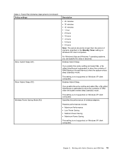
... to store the contents of RAM when the system enters sleep (standby) mode. This setting is generated to store the contents of RAM (Random Access Memory) when the system enters sleep (standby) mode. Specifies the performance of inactivity specified in seconds. If you can specify the value in the Standby Timer...
... to store the contents of RAM when the system enters sleep (standby) mode. This setting is generated to store the contents of RAM (Random Access Memory) when the system enters sleep (standby) mode. Specifies the performance of inactivity specified in seconds. If you can specify the value in the Standby Timer...
Hardware Maintenance Manual for ThinkCentre A85
Page 5
...computer cover 72 Removing and reinstalling the front bezel . . 73 Installing or replacing a PCI card 75 Installing or replacing a memory module . . . 78 Replacing the battery 80 Replacing the power supply assembly . . . 81 Replacing the heat sink and... 6 Grounding requirements 6 Safety notices (multi-lingual translations) . . . . . 6 Chapter 3. General information . . . . 29 Lenovo ThinkVantage Tools 29 Lenovo Welcome 29 Lenovo Solution Center 29 SimpleTap 29 Information resources 29 Specifications 29 Specifications: 0041, 0107, 0163, and 7543 . 30 Specifications: 0104, 0154, 7539...
...computer cover 72 Removing and reinstalling the front bezel . . 73 Installing or replacing a PCI card 75 Installing or replacing a memory module . . . 78 Replacing the battery 80 Replacing the power supply assembly . . . 81 Replacing the heat sink and... 6 Grounding requirements 6 Safety notices (multi-lingual translations) . . . . . 6 Chapter 3. General information . . . . 29 Lenovo ThinkVantage Tools 29 Lenovo Welcome 29 Lenovo Solution Center 29 SimpleTap 29 Information resources 29 Specifications 29 Specifications: 0041, 0107, 0163, and 7543 . 30 Specifications: 0104, 0154, 7539...

Hardware Maintenance Manual for ThinkCentre A85
Page 6
...and service 241 Information resources 241 Lenovo ThinkVantage Tools 241 Lenovo Welcome 241 Access Help 241 Safety and warranty 241 Lenovo Web site (http://www.lenovo.com) . . 242 Help ...the system board components and drives 109 Installing or replacing a PCI card 110 Installing or replacing a memory module . . . 113 Replacing the battery 115 Replacing the heat sink and fan assembly . ... Windows XP Professional 32 Recovery CD . . 186 Windows Vista Business 32 Recovery CD . . 187 iv ThinkCentre Hardware Maintenance Manual Overall: MT 0104, 0154, 7539, and 7548 . . . . 188 Mechanical FRUs ...
...and service 241 Information resources 241 Lenovo ThinkVantage Tools 241 Lenovo Welcome 241 Access Help 241 Safety and warranty 241 Lenovo Web site (http://www.lenovo.com) . . 242 Help ...the system board components and drives 109 Installing or replacing a PCI card 110 Installing or replacing a memory module . . . 113 Replacing the battery 115 Replacing the heat sink and fan assembly . ... Windows XP Professional 32 Recovery CD . . 186 Windows Vista Business 32 Recovery CD . . 187 iv ThinkCentre Hardware Maintenance Manual Overall: MT 0104, 0154, 7539, and 7548 . . . . 188 Mechanical FRUs ...

Hardware Maintenance Manual for ThinkCentre A85
Page 52
...page 237. 3. Flash the system. System board Information only Re-start the test to review the log file 2. Flash the system. Reboot the system 2. Run memory test 4. See "Updating (flashing) the BIOS from a disc" on page 237. 2. System board 1. System board 1. Flash the system. Re-start the test.... 3. Flash the system. See "Updating (flashing) the BIOS from a disc" on page 237. 2. Press F3 to reset the log file 44 ThinkCentre Hardware Maintenance Manual System board 1. System board 1. System board 1. System board 1. Run Setup 2. System board 1.
...page 237. 3. Flash the system. System board Information only Re-start the test to review the log file 2. Flash the system. Reboot the system 2. Run memory test 4. See "Updating (flashing) the BIOS from a disc" on page 237. 2. System board 1. System board 1. Flash the system. Re-start the test.... 3. Flash the system. See "Updating (flashing) the BIOS from a disc" on page 237. 2. Press F3 to reset the log file 44 ThinkCentre Hardware Maintenance Manual System board 1. System board 1. System board 1. System board 1. Run Setup 2. System board 1.

Hardware Maintenance Manual for ThinkCentre A85
Page 53
..." on page 39. 2. Make sure the component that is called out in warning statement 4. See "Updating (flashing) the BIOS from a disc" on page 64. 1. Run memory test 4. See Chapter 6 "Using the Setup Utility program" on page 39. 2. System board 1. Flash the system. System board System board System board Chapter 7. Replace the...
..." on page 39. 2. Make sure the component that is called out in warning statement 4. See "Updating (flashing) the BIOS from a disc" on page 64. 1. Run memory test 4. See Chapter 6 "Using the Setup Utility program" on page 39. 2. System board 1. Flash the system. System board System board System board Chapter 7. Replace the...
Hardware Maintenance Manual for ThinkCentre A85
Page 59
.... See Chapter 6 "Using the Setup Utility program" on page 237. 2. Replace the component under function test. 1. Remove USB device(s) and re-test 2. re-test. Run memory test 4. System board 1. Re-run test 3. Replace the component that is called out is called out, make sure it is connected and/or enabled 2. Flash...
.... See Chapter 6 "Using the Setup Utility program" on page 237. 2. Replace the component under function test. 1. Remove USB device(s) and re-test 2. re-test. Run memory test 4. System board 1. Re-run test 3. Replace the component that is called out is called out, make sure it is connected and/or enabled 2. Flash...

Hardware Maintenance Manual for ThinkCentre A85
Page 67
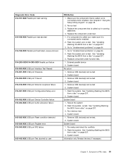
... error 185-000-XXX Asset Security Test Passed 185-XXX-XXX Asset Security failure 185-278-XXX Asset Security Chassis Intrusion 201-000-XXX System Memory Test Passed FRU/Action 1. See "Undetermined problems" on page 39. 2. Flash system 2. System board Information only Re-start the test to -FRU index 59 Press...
... error 185-000-XXX Asset Security Test Passed 185-XXX-XXX Asset Security failure 185-278-XXX Asset Security Chassis Intrusion 201-000-XXX System Memory Test Passed FRU/Action 1. See "Undetermined problems" on page 39. 2. Flash system 2. System board Information only Re-start the test to -FRU index 59 Press...

Hardware Maintenance Manual for ThinkCentre A85
Page 68
Replace the memory module called out by the test. 2. System board No action 1. CD-ROM drive 4. System board No action 1. Keyboard 2. System board No action No action 1. Check and test Keyboard 3. System board No action Remove the Joystick and re-test the system 60 ThinkCentre Hardware Maintenance Manual Cache.... 1. Check power supply voltages 3. Check power supply voltages 3. Hard Disk drive (SCSI) 5. Diagnostic Error Code 201-XXX-XXX System Memory error 202-000-XXX System Cache Test Passed 202-XXX-XXX System Cache error 206-000-XXX Diskette Drive Test Passed 206-XXX-XXX Diskette...
Replace the memory module called out by the test. 2. System board No action 1. CD-ROM drive 4. System board No action 1. Keyboard 2. System board No action No action 1. Check and test Keyboard 3. System board No action Remove the Joystick and re-test the system 60 ThinkCentre Hardware Maintenance Manual Cache.... 1. Check power supply voltages 3. Check power supply voltages 3. Hard Disk drive (SCSI) 5. Diagnostic Error Code 201-XXX-XXX System Memory error 202-000-XXX System Cache Test Passed 202-XXX-XXX System Cache error 206-000-XXX Diskette Drive Test Passed 206-XXX-XXX Diskette...
Hardware Maintenance Manual for ThinkCentre A85
Page 69
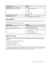
...When you turn on the screen the next time you correct the cause of the system and some basic system-board operations • Checks the memory operation • Starts the video operation • Verifies that check the operation of the first error message, the other error messages probably will ...the Modem and re-test the system Beep symptoms Beep symptoms are properly seated in "POST error codes" on the screen. Monitor 4. Make sure the memory module(s) are tones or a series of tests is working If the POST detects a problem, an error message appears on page 61. Cable 3. ...
...When you turn on the screen the next time you correct the cause of the system and some basic system-board operations • Checks the memory operation • Starts the video operation • Verifies that check the operation of the first error message, the other error messages probably will ...the Modem and re-test the system Beep symptoms Beep symptoms are properly seated in "POST error codes" on the screen. Monitor 4. Make sure the memory module(s) are tones or a series of tests is working If the POST detects a problem, an error message appears on page 61. Cable 3. ...

Hardware Maintenance Manual for ThinkCentre A85
Page 70
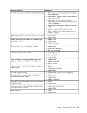
... Power Switch 2. Ensure that network adapter is kept pressed for RPL 3. Power off . System Board 3. No operating system found Memory size decreased Configuration change has occurred Press F10 to exit. Network adapter (Advise network administrator of the fingerprint keyboards except the one ... drive boot error" on your main operating system. Computer will not power-off and remove all of new MAC address) 62 ThinkCentre Hardware Maintenance Manual Riser card, if installed 1. The system might be displayed to remove all but the reader that network is completed...
... Power Switch 2. Ensure that network adapter is kept pressed for RPL 3. Power off . System Board 3. No operating system found Memory size decreased Configuration change has occurred Press F10 to exit. Network adapter (Advise network administrator of the fingerprint keyboards except the one ... drive boot error" on your main operating system. Computer will not power-off and remove all of new MAC address) 62 ThinkCentre Hardware Maintenance Manual Riser card, if installed 1. The system might be displayed to remove all but the reader that network is completed...
Hardware Maintenance Manual for ThinkCentre A85
Page 71
...Setup Utility program" on LAN feature is using correct MAC address 5. System Board Chapter 7. Power Supply 2. Hard Disk Drive Cable Incorrect memory size during POST 1. Non-system disk or disk error-type message with an otherwise blank display. 1. Diskette Drive Cable Other display ... Intensity or color varies from left to enable Wake on or does not light when drive is active. 1. System Board 3. Run the Memory tests 2. System Board 2. System Board No power or fan not running 1. Power switch/LED assembly 2. System Board Printer problems 1. Check...
...Setup Utility program" on LAN feature is using correct MAC address 5. System Board Chapter 7. Power Supply 2. Hard Disk Drive Cable Incorrect memory size during POST 1. Non-system disk or disk error-type message with an otherwise blank display. 1. Diskette Drive Cable Other display ... Intensity or color varies from left to enable Wake on or does not light when drive is active. 1. System Board 3. Run the Memory tests 2. System Board 2. System Board No power or fan not running 1. Power switch/LED assembly 2. System Board Printer problems 1. Check...

Hardware Maintenance Manual for ThinkCentre A85
Page 72
...RPL computer cannot access programs from server 1. External Device Self-Test OK? 2. Alternate Adapter 5. Keyboard Cable 3. Extended video memory e. network b. External Device 3. System Board Some or all keys on the power and the computer to re-test the...First device - Remove or disconnect the following : 1. Memory modules d. System Board Serial or parallel port device failure (adapter port) 1. System Board Undetermined problems If you find the failing device or adapter cards. 64 ThinkCentre Hardware Maintenance Manual Any adapter cards c. External Cache ...
...RPL computer cannot access programs from server 1. External Device Self-Test OK? 2. Alternate Adapter 5. Keyboard Cable 3. Extended video memory e. network b. External Device 3. System Board Some or all keys on the power and the computer to re-test the...First device - Remove or disconnect the following : 1. Memory modules d. System Board Serial or parallel port device failure (adapter port) 1. System Board Undetermined problems If you find the failing device or adapter cards. 64 ThinkCentre Hardware Maintenance Manual Any adapter cards c. External Cache ...
Hardware Maintenance Manual for ThinkCentre A85
Page 77
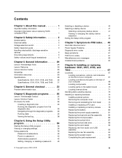
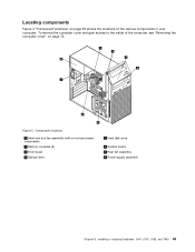
Locating components Figure 3 "Component locations" on page 69 shows the locations of the computer, see "Removing the computer cover" on page 72. Component locations 1 Heat sink and fan assembly (with a microprocessor underneath) 2 Memory modules (2) 3 Front bezel 4 Optical drive 5 Hard disk drive 6 System board 7 Rear fan assembly 8 Power supply assembly Chapter 8. Installing or replacing hardware: 0041, 0107, 0163, and 7543 69 Figure 3. To remove the computer cover and gain access to the inside of the various components in your computer.
Locating components Figure 3 "Component locations" on page 69 shows the locations of the computer, see "Removing the computer cover" on page 72. Component locations 1 Heat sink and fan assembly (with a microprocessor underneath) 2 Memory modules (2) 3 Front bezel 4 Optical drive 5 Hard disk drive 6 System board 7 Rear fan assembly 8 Power supply assembly Chapter 8. Installing or replacing hardware: 0041, 0107, 0163, and 7543 69 Figure 3. To remove the computer cover and gain access to the inside of the various components in your computer.
Hardware Maintenance Manual for ThinkCentre A85
Page 78
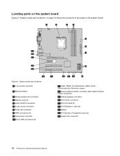
System board part locations 1 4-pin power connector 2 Microprocessor 3 Microprocessor fan connector 4 Memory slots (4) 5 Serial (COM 2) connector 6 24-pin power connector 7 Power fan connector 8 SATA connectors (4) 9 Front panel connector 10 Front USB connectors (2) 11 Clear CMOS (... connector 15 PCI card slots (2) 16 PCI Express x1 card slot 17 Battery 18 PCI Express x16 graphics card slot 19 System fan connector 70 ThinkCentre Hardware Maintenance Manual Figure 4. Locating parts on the system board Figure 4 "System board part locations" on page 70 shows the locations of the ...
System board part locations 1 4-pin power connector 2 Microprocessor 3 Microprocessor fan connector 4 Memory slots (4) 5 Serial (COM 2) connector 6 24-pin power connector 7 Power fan connector 8 SATA connectors (4) 9 Front panel connector 10 Front USB connectors (2) 11 Clear CMOS (... connector 15 PCI card slots (2) 16 PCI Express x1 card slot 17 Battery 18 PCI Express x16 graphics card slot 19 System fan connector 70 ThinkCentre Hardware Maintenance Manual Figure 4. Locating parts on the system board Figure 4 "System board part locations" on page 70 shows the locations of the ...

Hardware Maintenance Manual for ThinkCentre A85
Page 80
... or replacing hardware This section provides instructions on how to remove the computer cover. 72 ThinkCentre Hardware Maintenance Manual Handle PCI cards, memory modules, system boards, and microprocessors by Lenovo. 2. Then, use the appropriate instructions in this in addition to making the physical connection...must install additional software in your specific situation, place the static-protective package of the ThinkCentre Safety and Warranty Guide, go to: http://www.lenovo.com/support This section provides instructions on how to install or replace hardware for the ...
... or replacing hardware This section provides instructions on how to remove the computer cover. 72 ThinkCentre Hardware Maintenance Manual Handle PCI cards, memory modules, system boards, and microprocessors by Lenovo. 2. Then, use the appropriate instructions in this in addition to making the physical connection...must install additional software in your specific situation, place the static-protective package of the ThinkCentre Safety and Warranty Guide, go to: http://www.lenovo.com/support This section provides instructions on how to install or replace hardware for the ...


