

Hardware Maintenance Manual
Page 5
... Enhanced Diagnostics 13 Diagnostics program download 13 Running IBM Enhanced Diagnostics from a POST/BIOS update failure 148 Power management 150 Automatic configuration and power interface (ACPI) BIOS 150 iii Parts listing 91 Machine Type 8127 91 Machine Type 8183 95 Machine ... CMOS 146 Vital product data 146 Management Information Format (MIF) . . . 147 BIOS levels 147 Flash update procedures 148 Updating (flashing) BIOS from a diskette . . . 148 Updating (flashing) BIOS from your operating system 148 Recovering from the Access IBM Predesktop Area 13 Navigating through the...
... Enhanced Diagnostics 13 Diagnostics program download 13 Running IBM Enhanced Diagnostics from a POST/BIOS update failure 148 Power management 150 Automatic configuration and power interface (ACPI) BIOS 150 iii Parts listing 91 Machine Type 8127 91 Machine Type 8183 95 Machine ... CMOS 146 Vital product data 146 Management Information Format (MIF) . . . 147 BIOS levels 147 Flash update procedures 148 Updating (flashing) BIOS from a diskette . . . 148 Updating (flashing) BIOS from your operating system 148 Recovering from the Access IBM Predesktop Area 13 Navigating through the...

Hardware Maintenance Manual
Page 12
... 6 Hardware Maintenance Manual Video subsystem An integrated Intel Extreme Graphics 2 controller for an internal PCI modem) v Remote Administration v Automatic power-on startup v System Management (SM) BIOS and SM software v Ability to store POST hardware test results Input/output features v 25-pin, Extended Capabilities Port (ECP)/Extended Parallel Port (EPP) v Two 9-pin...
... 6 Hardware Maintenance Manual Video subsystem An integrated Intel Extreme Graphics 2 controller for an internal PCI modem) v Remote Administration v Automatic power-on startup v System Management (SM) BIOS and SM software v Ability to store POST hardware test results Input/output features v 25-pin, Extended Capabilities Port (ECP)/Extended Parallel Port (EPP) v Two 9-pin...

Hardware Maintenance Manual
Page 17
.... Make sure the system board is not recognized by the diagnostics program, that device might cause false errors and unnecessary replacement of BIOS is found by POST. Set all external devices. 6. Power-on page 49. Be extremely careful during write operations such as copying... finds a problem with a hardware option. For the test programs to Enhanced. Chapter 3. Attention The drives in the IBM Setup Utility program (see "BIOS levels" on the system. Data or programs can be defective. 001 1. See "Diagnostic error codes" on the computer. 7. General error messages appear ...
.... Make sure the system board is not recognized by the diagnostics program, that device might cause false errors and unnecessary replacement of BIOS is found by POST. Set all external devices. 6. Power-on page 49. Be extremely careful during write operations such as copying... finds a problem with a hardware option. For the test programs to Enhanced. Chapter 3. Attention The drives in the IBM Setup Utility program (see "BIOS levels" on the system. Data or programs can be defective. 001 1. See "Diagnostic error codes" on the computer. 7. General error messages appear ...

Hardware Maintenance Manual
Page 18
... Left Arrow (←) or Right Arrow (→) to 002 . v If you cannot continue, replace the last device tested. 12 Hardware Maintenance Manual Be sure APM BIOS Mode is set to Disabled. 7. Set Automatic Hardware Power Management to Disabled. Select APM. 4. Select Automatic Hardware Power Management. 6. v If the test stops and you...
... Left Arrow (←) or Right Arrow (→) to 002 . v If you cannot continue, replace the last device tested. 12 Hardware Maintenance Manual Be sure APM BIOS Mode is set to Disabled. 7. Set Automatic Hardware Power Management to Disabled. Select APM. 4. Select Automatic Hardware Power Management. 6. v If the test stops and you...

Hardware Maintenance Manual
Page 33
Open the cover. Rotate the drives upward as memory, the battery, and the Clear CMOS/BIOS recovery jumper, you disconnect from the riser card. See "Replacing a PCI adapter" on page 25. 3. You can also use this procedure to access the drives ...
Open the cover. Rotate the drives upward as memory, the battery, and the Clear CMOS/BIOS recovery jumper, you disconnect from the riser card. See "Replacing a PCI adapter" on page 25. 3. You can also use this procedure to access the drives ...

Hardware Maintenance Manual
Page 34
... panel connector disk drive connectors (2) 4 PCI riser connector 11 Power connector 5 Battery 12 PATA Primary IDE connector (hard disk drive and optical drive) 6 Clear CMOS/BIOS recovery 13 Power connector jumper 7 Speaker connector 14 Microprocessor 15 CD audio connector 28 Hardware Maintenance Manual The following illustration shows the locations of devices...
... panel connector disk drive connectors (2) 4 PCI riser connector 11 Power connector 5 Battery 12 PATA Primary IDE connector (hard disk drive and optical drive) 6 Clear CMOS/BIOS recovery 13 Power connector jumper 7 Speaker connector 14 Microprocessor 15 CD audio connector 28 Hardware Maintenance Manual The following illustration shows the locations of devices...

Hardware Maintenance Manual
Page 52
... no tools or loose screws are both in the locked position. Ensure that all components have replaced the system board, you must update (flash) the BIOS. Otherwise, you cannot close the cover and connect cables to the computer. Attention: To prevent overheating and possible component damage, always attach the floor stand...
... no tools or loose screws are both in the locked position. Ensure that all components have replaced the system board, you must update (flash) the BIOS. Otherwise, you cannot close the cover and connect cables to the computer. Attention: To prevent overheating and possible component damage, always attach the floor stand...

Hardware Maintenance Manual
Page 55
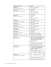
... procedures" on page 148 2. System board 1. Diagnostic error codes Refer to -FRU Index 49 Diagnostic Error Code 000-000-XXX BIOS Test Passed 000-002-XXX BIOS Timeout 000-024-XXX BIOS Addressing test failure 000-025-XXX BIOS Checksum Value error 000-026-XXX FLASH data error 000-027-XXX... BIOS Configuration/Setup error 000-034-XXX BIOS Buffer Allocation failure 000-035-XXX BIOS Reset Condition detected 000-036-XXX BIOS Register error 000-038-XXX BIOS Extension failure FRU/Action 1. Flash the system. Flash the system. No action 1. ...
... procedures" on page 148 2. System board 1. Diagnostic error codes Refer to -FRU Index 49 Diagnostic Error Code 000-000-XXX BIOS Test Passed 000-002-XXX BIOS Timeout 000-024-XXX BIOS Addressing test failure 000-025-XXX BIOS Checksum Value error 000-026-XXX FLASH data error 000-027-XXX... BIOS Configuration/Setup error 000-034-XXX BIOS Buffer Allocation failure 000-035-XXX BIOS Reset Condition detected 000-036-XXX BIOS Register error 000-038-XXX BIOS Extension failure FRU/Action 1. Flash the system. Flash the system. No action 1. ...

Hardware Maintenance Manual
Page 56
... Code 000-039-XXX BIOS DMI data error 000-195-XXX BIOS Test aborted by user 000-196-XXX BIOS test halt, error threshold exceeded 000-197-XXX BIOS test warning 000-198-XXX BIOS test aborted 000-199-XXX BIOS test failed, cause unknown 000-250-XXX BIOS APM failure 000-270-XXX BIOS ACPI failure 001...
... Code 000-039-XXX BIOS DMI data error 000-195-XXX BIOS Test aborted by user 000-196-XXX BIOS test halt, error threshold exceeded 000-197-XXX BIOS test warning 000-198-XXX BIOS test aborted 000-199-XXX BIOS test failed, cause unknown 000-250-XXX BIOS APM failure 000-270-XXX BIOS ACPI failure 001...
Hardware Maintenance Manual
Page 60
... error 005-031-XXX Video Device Cable failure 005-032-XXX Video Device Controller failure 005-036-XXX Video Register error 005-038-XXX System BIOS extension failure 005-040-XXX Video IRQ failure 005-195-XXX Video Test aborted by user 005-196-XXX Video test halt, error threshold exceeded...
... error 005-031-XXX Video Device Cable failure 005-032-XXX Video Device Controller failure 005-036-XXX Video Register error 005-038-XXX System BIOS extension failure 005-040-XXX Video IRQ failure 005-195-XXX Video Test aborted by user 005-196-XXX Video test halt, error threshold exceeded...

Hardware Maintenance Manual
Page 76
... 70 Hardware Maintenance Manual System Board 1. System Board 1. System Board 1. See the following table to diagnose beep symptoms. Beep Symptom 1-1-3 CMOS read-write error 1-2-2-3 ROM BIOS check error 1-2-1 Programmable Interval Timer failed 1-2-2 DMA Initialization failed 1-2-3 DMA page register write/read failed 1-2-4 RAM refresh verification failed 1-3-3-1 1st 64K RAM test failed 1-3-2 1st...
... 70 Hardware Maintenance Manual System Board 1. System Board 1. System Board 1. See the following table to diagnose beep symptoms. Beep Symptom 1-1-3 CMOS read-write error 1-2-2-3 ROM BIOS check error 1-2-1 Programmable Interval Timer failed 1-2-2 DMA Initialization failed 1-2-3 DMA page register write/read failed 1-2-4 RAM refresh verification failed 1-3-3-1 1st 64K RAM test failed 1-3-2 1st...

Hardware Maintenance Manual
Page 80
..., changed location? Time and Date Set 2. CMOS Backup Battery (see "Replacing the battery" on page 19.) 2. Check System Summary menu for the BIOS level needed, then perform the flash update. 2. Run the Extended Memory Diagnostic tests 1. System Board 1. Check Stepping level for memory size change. (...See "Starting the IBM Setup Utility program" on page 31) 3. C2 Security 1. Covers were removed from a POST/BIOS update failure" on page 19.. 2. CMOS Backup Battery (see "Replacing the battery" on LA™N error 17X, 18X 175 Primary Copy of Secure...
..., changed location? Time and Date Set 2. CMOS Backup Battery (see "Replacing the battery" on page 19.) 2. Check System Summary menu for the BIOS level needed, then perform the flash update. 2. Run the Extended Memory Diagnostic tests 1. System Board 1. Check Stepping level for memory size change. (...See "Starting the IBM Setup Utility program" on page 31) 3. C2 Security 1. Covers were removed from a POST/BIOS update failure" on page 19.. 2. CMOS Backup Battery (see "Replacing the battery" on LA™N error 17X, 18X 175 Primary Copy of Secure...
Hardware Maintenance Manual
Page 151
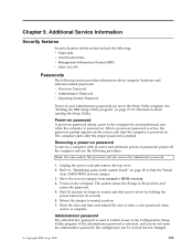
... beeps to ROM recovery. 4. Return the jumper to enter a new password when service is powered on password denies access to find the Virtual clear CMOS/BIOS recovery jumper. 3. Reset the date and time and remind the user to normal position. 7. Power-on password A power-on . Note: On some models, this section...
... beeps to ROM recovery. 4. Return the jumper to enter a new password when service is powered on password denies access to find the Virtual clear CMOS/BIOS recovery jumper. 3. Reset the date and time and remind the user to normal position. 7. Power-on password A power-on . Note: On some models, this section...

Hardware Maintenance Manual
Page 152
... you replace the system board, the VPD must be entered to "Identifying parts on the system board" on page 46. Locate the Clear CMOS/BIOS recovery jumper on page 19. Lower the drives and reconnect any cables that were disconnected. 6. Refer to use the computer. See "Closing the cover...: This computer has Enhanced Security Mode. See "Closing the cover and connecting the cables" on the POV card and cannot be updated. Move the CMOS/BIOS recovery jumper back to the maintenance or configure position (pins 2 and 3). 4. In these models, the password is lost or forgotten, the system board...
... you replace the system board, the VPD must be entered to "Identifying parts on the system board" on page 46. Locate the Clear CMOS/BIOS recovery jumper on page 19. Lower the drives and reconnect any cables that were disconnected. 6. Refer to use the computer. See "Closing the cover...: This computer has Enhanced Security Mode. See "Closing the cover and connecting the cables" on the POV card and cannot be updated. Move the CMOS/BIOS recovery jumper back to the maintenance or configure position (pins 2 and 3). 4. In these models, the password is lost or forgotten, the system board...

Hardware Maintenance Manual
Page 153
... servicer can cause false errors and unnecessary FRU replacement. Click Start from Retain-a-Group. Enter new data in the EPROM. v Current Level BIOS information - IBM PC support web site: http://www.ibm.com/pc/support/ 2. Management Information Format (MIF) Management Information Format (MIF)... you want to law enforcement. IBM Support Center 3. Levels 1 and 2 Support 4. ® RETAIN v Sources for determining the latest level BIOS available 1. IBM Support Center 3. Click the plus sign to change. 7. IBM PC support web site:http://www.ibm.com/pc/support/ 2....
... servicer can cause false errors and unnecessary FRU replacement. Click Start from Retain-a-Group. Enter new data in the EPROM. v Current Level BIOS information - IBM PC support web site: http://www.ibm.com/pc/support/ 2. Management Information Format (MIF) Management Information Format (MIF)... you want to law enforcement. IBM Support Center 3. Levels 1 and 2 Support 4. ® RETAIN v Sources for determining the latest level BIOS available 1. IBM Support Center 3. Click the plus sign to change. 7. IBM PC support web site:http://www.ibm.com/pc/support/ 2....

Hardware Maintenance Manual
Page 154
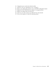
... to change. 1. See "Opening the cover" on the system board. Locate the Clear CMOS/Recovery jumper on page 25. 3. Insert the POST/BIOS update (flash) diskette into the diskette drive (drive A) in the address field and press Enter. 2. After the update session is completed, there...power cords from a diskette 1. If this happens, perform the following procedure) is on the World Wide Web. 2. Replace the cover. BIOS by category, click BIOS. 5. Scroll down and look for your machine type and click Go. 4. Turn off the computer and monitor. 148 Hardware Maintenance Manual ...
... to change. 1. See "Opening the cover" on the system board. Locate the Clear CMOS/Recovery jumper on page 25. 3. Insert the POST/BIOS update (flash) diskette into the diskette drive (drive A) in the address field and press Enter. 2. After the update session is completed, there...power cords from a diskette 1. If this happens, perform the following procedure) is on the World Wide Web. 2. Replace the cover. BIOS by category, click BIOS. 5. Scroll down and look for your machine type and click Go. 4. Turn off the computer and monitor. 148 Hardware Maintenance Manual ...
Hardware Maintenance Manual
Page 155
See "Opening the cover" on the computer to restart the operating system. Open the cover. Remove any adapters that were removed. 15. 10. Replace any adapters that were disconnected. 16. Turn on page 25. 12. Chapter 9. Additional Service Information 149 Replace the Clear CMOS/Recovery jumper to the BIOS Configuration jumper. 13. Close the cover and reconnect any cables that impede access to its original position. 14. Unplug the power cords from electrical outlets. 11.
See "Opening the cover" on the computer to restart the operating system. Open the cover. Remove any adapters that were removed. 15. 10. Replace any adapters that were disconnected. 16. Turn on page 25. 12. Chapter 9. Additional Service Information 149 Replace the Clear CMOS/Recovery jumper to the BIOS Configuration jumper. 13. Close the cover and reconnect any cables that impede access to its original position. 14. Unplug the power cords from electrical outlets. 11.

Hardware Maintenance Manual
Page 156
...saving settings can be viewed and changed by specifying values for the following options. Set the time for Advanced Power Management (APM) BIOS mode are ignored. v System Power - On some monitors, you might have power-management capabilities, it supports Display Power Management ...Signaling (DPMS). Not all operating systems support ACPI BIOS mode. Select On for the monitor, check the documentation supplied with the monitor to see "Starting the IBM Setup Utility program" on ...
...saving settings can be viewed and changed by specifying values for the following options. Set the time for Advanced Power Management (APM) BIOS mode are ignored. v System Power - On some monitors, you might have power-management capabilities, it supports Display Power Management ...Signaling (DPMS). Not all operating systems support ACPI BIOS mode. Select On for the monitor, check the documentation supplied with the monitor to see "Starting the IBM Setup Utility program" on ...

Hardware Maintenance Manual
Page 157
... (←) or Right Arrow (→) to Enabled, the computer will turn on when it receives a specific signal from another computer on the modem. Select APM BIOS Mode within the Power Management menu allow PCI cards that is Wake on the computer automatically. Set Automatic Hardware Power Management to Enabled or Disabled...
... (←) or Right Arrow (→) to Enabled, the computer will turn on when it receives a specific signal from another computer on the modem. Select APM BIOS Mode within the Power Management menu allow PCI cards that is Wake on the computer automatically. Set Automatic Hardware Power Management to Enabled or Disabled...
Hardware Maintenance Manual
Page 193
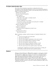
...it has been working ″ systems will often lead to problem resolution. What, when, where, single, or multiple systems? - Have the same BIOS level 3. Problem determination tips Due to the variety of hardware and software combinations that can be encountered, use - v Machine type and model v ...not imply that IBM intends to make these available in all countries in use the following information to assist you in the same locations 4. BIOS level v Operating system software - Have the same configuration options set -up between ″working and non-working , what changes were ...
...it has been working ″ systems will often lead to problem resolution. What, when, where, single, or multiple systems? - Have the same BIOS level 3. Problem determination tips Due to the variety of hardware and software combinations that can be encountered, use - v Machine type and model v ...not imply that IBM intends to make these available in all countries in use the following information to assist you in the same locations 4. BIOS level v Operating system software - Have the same configuration options set -up between ″working and non-working , what changes were ...


