User Guide
Page 5
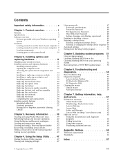
... Setup Utility program 47 Viewing and changing settings 47 Using passwords 47 Password considerations 48 Power-On Password 48 Privileged Access Password 48 Hard Disk User Password 48 Setting, changing,...Appendix. Notices 65 Television output notice 66 Trademarks 66 Index 67 © Copyright Lenovo 2009 iii Installing options and replacing hardware 11 Handling static-sensitive devices 11 Installing options...Installing or replacing a memory module . . . 14 Installing or replacing an adapter card . . . . 16 Installing internal drives 18 Replacing the hard disk drive 22...
... Setup Utility program 47 Viewing and changing settings 47 Using passwords 47 Password considerations 48 Power-On Password 48 Privileged Access Password 48 Hard Disk User Password 48 Setting, changing,...Appendix. Notices 65 Television output notice 66 Trademarks 66 Index 67 © Copyright Lenovo 2009 iii Installing options and replacing hardware 11 Handling static-sensitive devices 11 Installing options...Installing or replacing a memory module . . . 14 Installing or replacing an adapter card . . . . 16 Installing internal drives 18 Replacing the hard disk drive 22...
User Guide
Page 10
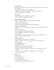
...) Connectivity v 10/100/1000 Mbps integrated Ethernet controller v PCI V.90 Data/Fax modem (some models) System management features v Ability to store power-on self-test (POST) hardware test results v Automatic power-on startup v ASF 2.0 (Alert Standard Format) v Intel Active Management Technology (AMT) (some models) v Intel matrix storage manager v Preboot Execution Environment (PXE... headphone) on the front panel v VGA monitor connector Expansion v One card reader v One hard disk drive bay v One optical drive bay v One 32-bit PCI adapter card slot v One PCI Express x16 graphics...
...) Connectivity v 10/100/1000 Mbps integrated Ethernet controller v PCI V.90 Data/Fax modem (some models) System management features v Ability to store power-on self-test (POST) hardware test results v Automatic power-on startup v ASF 2.0 (Alert Standard Format) v Intel Active Management Technology (AMT) (some models) v Intel matrix storage manager v Preboot Execution Environment (PXE... headphone) on the front panel v VGA monitor connector Expansion v One card reader v One hard disk drive bay v One optical drive bay v One 32-bit PCI adapter card slot v One PCI Express x16 graphics...
User Guide
Page 15
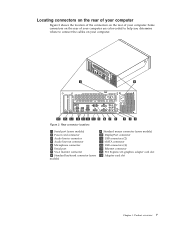
... connectors on the rear of your computer Figure 2 shows the location of your computer. Rear connector locations 1 Serial port (some models) 2 Power cord connector 3 Audio line-in connector 4 Audio line-out connector 5 Microphone connector 6 Serial port 7 VGA monitor connector 8 Standard keyboard connector... 10 DisplayPort connector 11 USB connectors (2) 12 eSATA connector 13 USB connectors (4) 14 Ethernet connector 15 PCI Express x16 graphics adapter card slot 16 Adapter card slot Chapter 1. Product overview 7 Figure 2. Some connectors on the rear of your computer are color-coded to help...
... connectors on the rear of your computer Figure 2 shows the location of your computer. Rear connector locations 1 Serial port (some models) 2 Power cord connector 3 Audio line-in connector 4 Audio line-out connector 5 Microphone connector 6 Serial port 7 VGA monitor connector 8 Standard keyboard connector... 10 DisplayPort connector 11 USB connectors (2) 12 eSATA connector 13 USB connectors (4) 14 Ethernet connector 15 PCI Express x16 graphics adapter card slot 16 Adapter card slot Chapter 1. Product overview 7 Figure 2. Some connectors on the rear of your computer are color-coded to help...

User Guide
Page 18
...system board Figure 4 shows the location of the parts on the system board. System board parts locations 1 PCI adapter card slot 2 PCI Express x16 graphics adapter card slot 3 Battery 4 Internal speaker connector 5 Cover presence switch (also called Intrusion switch) connector 6 Microprocessor ...fan connector 7 Thermal sensor connector 8 Microprocessor 9 4-pin power connector 10 Front panel connector 11 Memory slots (4) 12 24-pin power connector 13...
...system board Figure 4 shows the location of the parts on the system board. System board parts locations 1 PCI adapter card slot 2 PCI Express x16 graphics adapter card slot 3 Battery 4 Internal speaker connector 5 Cover presence switch (also called Intrusion switch) connector 6 Microprocessor ...fan connector 7 Thermal sensor connector 8 Microprocessor 9 4-pin power connector 10 Front panel connector 11 Memory slots (4) 12 24-pin power connector 13...


