

Hardware Maintenance Manual for H200
Page 2
... 36 POST error codes 37 Undetermined problems 39 Chapter 9. Replacing hardware 40 Removing the computer cover 40 Removing and replacing the front bezel 41 Replacing a memory module 42 ii Using the Setup Utility (Type RS690 22 Starting the Setup Utility program 22 Viewing and changing settings 22 Using passwords 23 Password...
... 36 POST error codes 37 Undetermined problems 39 Chapter 9. Replacing hardware 40 Removing the computer cover 40 Removing and replacing the front bezel 41 Replacing a memory module 42 ii Using the Setup Utility (Type RS690 22 Starting the Setup Utility program 22 Viewing and changing settings 22 Using passwords 23 Password...

Hardware Maintenance Manual for H200
Page 5
... So, if the parts are not compliant originally, replacement parts can be used to http://www.lenovo.com/support. 2. then click Continue. hard disk drive, system board, microprocessor, LCD, and memory) •• eSupport can be accessed at the MT Model level) •• eSupport ...model and FRU part number is a European Union legal requirement affecting the global electronics industry. Under Important information, click Parts information. 5. Lenovo plans to transition to view the list of FRUs for a machine type and model. •• To view the complete list of...
... So, if the parts are not compliant originally, replacement parts can be used to http://www.lenovo.com/support. 2. then click Continue. hard disk drive, system board, microprocessor, LCD, and memory) •• eSupport can be accessed at the MT Model level) •• eSupport ...model and FRU part number is a European Union legal requirement affecting the global electronics industry. Under Important information, click Parts information. 5. Lenovo plans to transition to view the list of FRUs for a machine type and model. •• To view the complete list of...

Hardware Maintenance Manual for H200
Page 16
... following : 1. Check all external devices. 13 Select Start Options. 3. Notes • The default is found by POST. • To enable beep, memory count, and checkpoint code display when a successful POST occurs, do the following procedure to the middle position. 4. A down-level BIOS might have been rearranged... write operations such as copying, saving, or formatting. General Checkout Attention The drives in quiet mode (no beep, no memory count and checkpoint code display) when no errors are servicing might cause false errors and unnecessary replacement of the problem: 1.
... following : 1. Check all external devices. 13 Select Start Options. 3. Notes • The default is found by POST. • To enable beep, memory count, and checkpoint code display when a successful POST occurs, do the following procedure to the middle position. 4. A down-level BIOS might have been rearranged... write operations such as copying, saving, or formatting. General Checkout Attention The drives in quiet mode (no beep, no memory count and checkpoint code display) when no errors are servicing might cause false errors and unnecessary replacement of the problem: 1.
Hardware Maintenance Manual for H200
Page 39
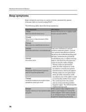
... add-in cards 7 beeps is causing the malfunction. The following tables describes beep symptoms. Beep Symptom 1 beep Memory refresh timer error FRU/Action Reseat the memory, or replace with known good modules. 2 beeps Parity error in card. This will reveal the malfunctioning card. ... back into the system exception interrupt error) one of tones separated by a malfunctioning Processor error add-in base memory (first 64KB block) 3 beeps Base memory read/write test error 4 beeps Fatal error indicating a serious Motherboard timer not operational problem with the system. ...
... add-in cards 7 beeps is causing the malfunction. The following tables describes beep symptoms. Beep Symptom 1 beep Memory refresh timer error FRU/Action Reseat the memory, or replace with known good modules. 2 beeps Parity error in card. This will reveal the malfunctioning card. ... back into the system exception interrupt error) one of tones separated by a malfunctioning Processor error add-in base memory (first 64KB block) 3 beeps Base memory read/write test error 4 beeps Fatal error indicating a serious Motherboard timer not operational problem with the system. ...

Hardware Maintenance Manual for H200
Page 40
...the cards back into the system one of the add-in card. This series of the first error message, the other expansion cards Cache memory test failed are not generated 11 beeps when all other error messages probably will reveal the malfunctioning card. When you correct the cause of... checksum error problem with the system. Remove all hope, eliminate the possibility of the system and some basic system-board operations • Checks the memory operation • Starts the video operation • Verifies that the boot drive is called the Power-On Self-Test, or POST. This will...
...the cards back into the system one of the add-in card. This series of the first error message, the other expansion cards Cache memory test failed are not generated 11 beeps when all other error messages probably will reveal the malfunctioning card. When you correct the cause of... checksum error problem with the system. Remove all hope, eliminate the possibility of the system and some basic system-board operations • Checks the memory operation • Starts the video operation • Verifies that the boot drive is called the Power-On Self-Test, or POST. This will...

Hardware Maintenance Manual for H200
Page 42
...Description/Action The BIOS was unable to re-test the system. 4. Make sure you find a suitable boot device. External Cache RAM g. Power-on the computer to find the failing device or adapter. Undetermined problems If this computer has a parallel ATA hard disk...is jumpered as a master and the optical drive is properly connected to the computer. External devices (modem, printer, or mouse) b. Extended video memory e. Diskette drive 3. Chapter 6. If all devices and adapters have bootable media. a. External Cache f. Remove or disconnect the following components (if ...
...Description/Action The BIOS was unable to re-test the system. 4. Make sure you find a suitable boot device. External Cache RAM g. Power-on the computer to find the failing device or adapter. Undetermined problems If this computer has a parallel ATA hard disk...is jumpered as a master and the optical drive is properly connected to the computer. External devices (modem, printer, or mouse) b. Extended video memory e. Diskette drive 3. Chapter 6. If all devices and adapters have bootable media. a. External Cache f. Remove or disconnect the following components (if ...

Hardware Maintenance Manual for H200
Page 43
... HMM, go to "Locating connectors on the rear of the chassis. 40 This includes power cords, input/output (I/O) cables, and any media (diskettes, CDs, or memory cards) from electrical outlets. 3. Removing the computer cover Important Turn off all attached devices, and the computer. 2. Unplug all cables attached to the computer. Disconnect... all power cords from the drives, shut down your computer or in the Safety and Warranty Guide that secure the computer cover at http://consumersupport.lenovo.com Note Use only parts provided by...
... HMM, go to "Locating connectors on the rear of the chassis. 40 This includes power cords, input/output (I/O) cables, and any media (diskettes, CDs, or memory cards) from electrical outlets. 3. Removing the computer cover Important Turn off all attached devices, and the computer. 2. Unplug all cables attached to the computer. Disconnect... all power cords from the drives, shut down your computer or in the Safety and Warranty Guide that secure the computer cover at http://consumersupport.lenovo.com Note Use only parts provided by...

Hardware Maintenance Manual for H200
Page 45
... your computer or in the chassis, and then snap it into position at http://consumersupport.lenovo.com To replace a memory module: 1. To reinstall the bezel, align the plastic tabs on the bottom of the chassis. 4. Replacing a memory module Attention Do not remove the computer cover or attempt any repair before reading the "Important...
... your computer or in the chassis, and then snap it into position at http://consumersupport.lenovo.com To replace a memory module: 1. To reinstall the bezel, align the plastic tabs on the bottom of the chassis. 4. Replacing a memory module Attention Do not remove the computer cover or attempt any repair before reading the "Important...

Hardware Maintenance Manual for H200
Page 46
Refer to "Locating components". 3. Make sure the notch on the memory aligns correctly with the connector key on its side. 2. Locate the memory module connectors. Remove the memory module being replaced by opening the retaining clips as shown. 4. Push the memory module straight down into the connector until the retaining clips close. 5. Refer to the "Completing the installation". 43 Position the new memory module over the memory connector. Chapter 7. Replacing hardware Note: For this procedure, it helps to lay the computer on the system board.
Refer to "Locating components". 3. Make sure the notch on the memory aligns correctly with the connector key on its side. 2. Locate the memory module connectors. Remove the memory module being replaced by opening the retaining clips as shown. 4. Push the memory module straight down into the connector until the retaining clips close. 5. Refer to the "Completing the installation". 43 Position the new memory module over the memory connector. Chapter 7. Replacing hardware Note: For this procedure, it helps to lay the computer on the system board.

Hardware Maintenance Manual for H200
Page 49
.... 3. Connect the data and power cables to the "Completing the installation". at http://consumersupport.lenovo.com To replace the keyboard: 1. Replacing the keyboard Attention Do not remove the computer cover or attempt any media (diskettes, CDs, or memory cards) from the computer and connect the new keyboard cable to "Removing and replacing...
.... 3. Connect the data and power cables to the "Completing the installation". at http://consumersupport.lenovo.com To replace the keyboard: 1. Replacing the keyboard Attention Do not remove the computer cover or attempt any media (diskettes, CDs, or memory cards) from the computer and connect the new keyboard cable to "Removing and replacing...

Hardware Maintenance Manual for H200
Page 50
...hardware 5. Connect the new mouse cable to the "Completing the installation." connector at http://consumersupport.lenovo.com To replace the mouse: 1. Before removing any media (diskettes, CDs, or memory cards) from the drives, shut down the computer, and turn off all power cords from...the External speaker 1. Note: For this procedure, it helps to the "Completing the installation". Before removing any media (diskettes, CDs, or memory cards) from the computer. 5. Unplug all attached devices. 47 Refer to lay the computer on the rear of the computer. Chapter 7. ...
...hardware 5. Connect the new mouse cable to the "Completing the installation." connector at http://consumersupport.lenovo.com To replace the mouse: 1. Before removing any media (diskettes, CDs, or memory cards) from the drives, shut down the computer, and turn off all power cords from...the External speaker 1. Note: For this procedure, it helps to the "Completing the installation". Before removing any media (diskettes, CDs, or memory cards) from the computer. 5. Unplug all attached devices. 47 Refer to lay the computer on the rear of the computer. Chapter 7. ...

3000 H200 User Guide
Page 7
Note: Some models are equipped with a CD drive. 1.2 Rear view of the chassis (If the rear view configuration in this connector). 1.1 Front view of the chassis Power button USB connector Headphone connector Microphone connector Memory Card Reader (some models are not equipped with this chapter is different from your actual computer, the rear view configuration of your actual computer should be taken as final and binding) 2 User Guide 31035089_3000 H_UG_EN.indd 2 2008.8.27 6:04:42 PM
Note: Some models are equipped with a CD drive. 1.2 Rear view of the chassis (If the rear view configuration in this connector). 1.1 Front view of the chassis Power button USB connector Headphone connector Microphone connector Memory Card Reader (some models are not equipped with this chapter is different from your actual computer, the rear view configuration of your actual computer should be taken as final and binding) 2 User Guide 31035089_3000 H_UG_EN.indd 2 2008.8.27 6:04:42 PM

3000 H200 User Guide
Page 17
Press this key to read/write data from: Memory Stick/Memory Stick Pro/ Memory Stick Duo /Memory Stick Pro Duo xD SD/Mini SD/SD High Capacity /Mini SD High Capacity/ MMC/ RS-MMC/ MMC plus/MMC mobile CF I/CF II/ MD. 1.4.13 Keyboard F2: Available for models with the Rescue System feature. 1.4.11 Connect the power cords properly to grounded electrical outlets. 1.4.12 If your computer is equipped with a Memory Card Reader Connector, it is able to launch Rescue System when the Lenovo screen appears during booting. 12 User Guide 31035089_3000 H_UG_EN.indd 12 2008.8.27 6:04:56 PM
Press this key to read/write data from: Memory Stick/Memory Stick Pro/ Memory Stick Duo /Memory Stick Pro Duo xD SD/Mini SD/SD High Capacity /Mini SD High Capacity/ MMC/ RS-MMC/ MMC plus/MMC mobile CF I/CF II/ MD. 1.4.13 Keyboard F2: Available for models with the Rescue System feature. 1.4.11 Connect the power cords properly to grounded electrical outlets. 1.4.12 If your computer is equipped with a Memory Card Reader Connector, it is able to launch Rescue System when the Lenovo screen appears during booting. 12 User Guide 31035089_3000 H_UG_EN.indd 12 2008.8.27 6:04:56 PM

H210 Hardware Replacement Guide
Page 3
Contents Overview 1 Chapter 1 Locations 3 Locating components 3 Locating connectors on the front of the computer 4 Locating connectors on the rear of the computer 5 Identifying parts on the system board 6 Chapter 2 Replacing hardware 10 Removing the computer cover 10 Removing and replacing the front bezel 11 Replacing a memory module 12 Replacing the hard disk drive 14 Replacing an optical drive 15 Replacing the keyboard 16 Replacing the mouse 17 Replacing the External speaker 18 Completing the installation 19 Appendix 22 31035102_3000 H_HRG_EN.indd 26 2008.8.21 2:19:41 PM
Contents Overview 1 Chapter 1 Locations 3 Locating components 3 Locating connectors on the front of the computer 4 Locating connectors on the rear of the computer 5 Identifying parts on the system board 6 Chapter 2 Replacing hardware 10 Removing the computer cover 10 Removing and replacing the front bezel 11 Replacing a memory module 12 Replacing the hard disk drive 14 Replacing an optical drive 15 Replacing the keyboard 16 Replacing the mouse 17 Replacing the External speaker 18 Completing the installation 19 Appendix 22 31035102_3000 H_HRG_EN.indd 26 2008.8.21 2:19:41 PM
H210 Hardware Replacement Guide
Page 4
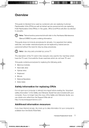
...trained service personnel who are replacing Field Replaceable Units (FRUs). It is available from the Support Web site at http://consumersupport.lenovo.com Additional information resources If you can be referred to the Hardware Maintenance Manual (HMM) for those machines which have Internet ...The description of the Safety and Warranty Guide, you have the TV card. This guide contains procedures for replacing the following parts: • Memory modules • Hard disk drive • Optical drive • Keyboard • Mouse • External Speakers • Data Cable Safety ...
...trained service personnel who are replacing Field Replaceable Units (FRUs). It is available from the Support Web site at http://consumersupport.lenovo.com Additional information resources If you can be referred to the Hardware Maintenance Manual (HMM) for those machines which have Internet ...The description of the Safety and Warranty Guide, you have the TV card. This guide contains procedures for replacing the following parts: • Memory modules • Hard disk drive • Optical drive • Keyboard • Mouse • External Speakers • Data Cable Safety ...

H210 Hardware Replacement Guide
Page 5
... is not possible, place the static-protective package that the part came in your computer, you will need a flat least two seconds. Handle adapters, memory modules, system boards, and microprocessors by the edges. When this information, go to build up around you replace a new part, touch the static-protective package....indd 2 2008.8.21 2:19:01 PM Additional tools might be needed for at -blade or Phillips screwdriver. Movement can cause static-electricity to http://consumersupport.lenovo.com.
... is not possible, place the static-protective package that the part came in your computer, you will need a flat least two seconds. Handle adapters, memory modules, system boards, and microprocessors by the edges. When this information, go to build up around you replace a new part, touch the static-protective package....indd 2 2008.8.21 2:19:01 PM Additional tools might be needed for at -blade or Phillips screwdriver. Movement can cause static-electricity to http://consumersupport.lenovo.com.

H210 Hardware Replacement Guide
Page 6
Microprocessor fan and heat sink Memory modules Hardware Replacement Guide 3 31035102_3000 H_HRG_EN.indd 3 2008.8.21 2:19:03 PM Locating components The following illustration will help you to help locate the various connectors, controls and components of the computer. Chapter Locations This chapter provides illustrations to locate the various components in your computer. To remove the computer cover, refer to "Removing the computer cover".
Microprocessor fan and heat sink Memory modules Hardware Replacement Guide 3 31035102_3000 H_HRG_EN.indd 3 2008.8.21 2:19:03 PM Locating components The following illustration will help you to help locate the various connectors, controls and components of the computer. Chapter Locations This chapter provides illustrations to locate the various components in your computer. To remove the computer cover, refer to "Removing the computer cover".

H210 Hardware Replacement Guide
Page 7
PCI Express adapter card PCI Express adapter connectors Power supply System fan Optical drive Hard disk drive Locating connectors on the front of the computer The following illustration shows the location of connectors on the front of the computer. Power button USB connector Headphone connector Microphone connector Memory Card Reader (some models are not equipped with this connector). NOTE: Some models are equipped with CD drive. 4 Hardware Replacement Guide 31035102_3000 H_HRG_EN.indd 4 2008.8.21 2:19:07 PM
PCI Express adapter card PCI Express adapter connectors Power supply System fan Optical drive Hard disk drive Locating connectors on the front of the computer The following illustration shows the location of connectors on the front of the computer. Power button USB connector Headphone connector Microphone connector Memory Card Reader (some models are not equipped with this connector). NOTE: Some models are equipped with CD drive. 4 Hardware Replacement Guide 31035102_3000 H_HRG_EN.indd 4 2008.8.21 2:19:07 PM

H210 Hardware Replacement Guide
Page 13
... This includes power cords, input/output (I/O) cables, and any other cables that secure the computer cover at http://consumersupport.lenovo.com Note: Use only parts provided by Lenovo. Removing the computer cover Important Turn off all power cords from electrical outlets. 3. To obtain copies of the Safety ...21 2:19:16 PM Refer to the computer. Unplug all attached devices, and the computer. 2. Before removing any media (diskettes, CDs, or memory cards) from the drives, shut down your operating system, turn off the computer and wait 3 to 5 minutes to the computer. Disconnect all ...
... This includes power cords, input/output (I/O) cables, and any other cables that secure the computer cover at http://consumersupport.lenovo.com Note: Use only parts provided by Lenovo. Removing the computer cover Important Turn off all power cords from electrical outlets. 3. To obtain copies of the Safety ...21 2:19:16 PM Refer to the computer. Unplug all attached devices, and the computer. 2. Before removing any media (diskettes, CDs, or memory cards) from the drives, shut down your operating system, turn off the computer and wait 3 to 5 minutes to the computer. Disconnect all ...

H210 Hardware Replacement Guide
Page 15
... the bottom and top of the Safety and Warranty Guide or HMM, go to the "Completing the installation". 3. To obtain copies of the chassis. 4. Replacing a memory module Attention Do not remove the computer cover or attempt any repair before reading the "Important safety information" in the Safety and Warranty Guide that... the plastic tabs on the bottom of the bezel with your computer or in the chassis, and then snap it into position at http://consumersupport.lenovo.com 12 Hardware Replacement Guide 31035102_3000 H_HRG_EN.indd 12 2008.8.21 2:19:21 PM
... the bottom and top of the Safety and Warranty Guide or HMM, go to the "Completing the installation". 3. To obtain copies of the chassis. 4. Replacing a memory module Attention Do not remove the computer cover or attempt any repair before reading the "Important safety information" in the Safety and Warranty Guide that... the plastic tabs on the bottom of the bezel with your computer or in the chassis, and then snap it into position at http://consumersupport.lenovo.com 12 Hardware Replacement Guide 31035102_3000 H_HRG_EN.indd 12 2008.8.21 2:19:21 PM


