Hardware Maintenance Manual
Page 3
... password 24 Power management 25 Screen blank mode 25 Sleep (standby) mode 25 Hibernation mode 26 Lenovo G470/G475/G570/G575 27 Specifications 27 Status indicators 29 Fn key combinations 31 FRU replacement notices 32 Screw notices 32 Removing and replacing an FRU 33 1010 Battery pack 34 1020 Dummy cards 35 1030...
... password 24 Power management 25 Screen blank mode 25 Sleep (standby) mode 25 Hibernation mode 26 Lenovo G470/G475/G570/G575 27 Specifications 27 Status indicators 29 Fn key combinations 31 FRU replacement notices 32 Screw notices 32 Removing and replacing an FRU 33 1010 Battery pack 34 1020 Dummy cards 35 1030...

Hardware Maintenance Manual
Page 9
... you in good condition. Check for any obvious unsafe conditions, such as metal filings, contamination, water or other liquids, or signs of non-Lenovo features or options not covered by this inspection guide is to measure third-wire ground continuity for worn, frayed, or pinched cables. 9. A ... present, you must not be the type specified in the parts list. Check for any unsafe conditions are any non-Lenovo alterations. 7. Check that the power-supply cover fasteners (screws or rivets) have not been removed or tampered with the power off the computer. If any obvious non...
... you in good condition. Check for any obvious unsafe conditions, such as metal filings, contamination, water or other liquids, or signs of non-Lenovo features or options not covered by this inspection guide is to measure third-wire ground continuity for worn, frayed, or pinched cables. 9. A ... present, you must not be the type specified in the parts list. Check for any unsafe conditions are any non-Lenovo alterations. 7. Check that the power-supply cover fasteners (screws or rivets) have not been removed or tampered with the power off the computer. If any obvious non...

Hardware Maintenance Manual
Page 23
... recurs. If the error does not recur, do with a hardware defect, such as copying, saving, or formatting. If you replace FRUs, use new nylon-coated screws. • Be extremely careful during such write operations as cosmic radiation, electrostatic discharge, or software errors. Single failures can service the computer. • Before replacing...
... recurs. If the error does not recur, do with a hardware defect, such as copying, saving, or formatting. If you replace FRUs, use new nylon-coated screws. • Be extremely careful during such write operations as cosmic radiation, electrostatic discharge, or software errors. Single failures can service the computer. • Before replacing...
Hardware Maintenance Manual
Page 36
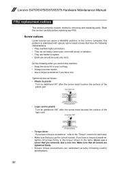
...you have one . Never use the correct screws. Read this machine: •• Keep the screw kit in the table. Use a new one . Make sure that all screws firmly to removing and replacing parts. Lenovo G470/G475/G570/G575 Hardware Maintenance Manual FRU replacement notices This section ...presents notices related to the torque shown in your tool bag. •• Always use new screws. •• Use a torque...
...you have one . Never use the correct screws. Read this machine: •• Keep the screw kit in the table. Use a new one . Make sure that all screws firmly to removing and replacing parts. Lenovo G470/G475/G570/G575 Hardware Maintenance Manual FRU replacement notices This section ...presents notices related to the torque shown in your tool bag. •• Always use new screws. •• Use a torque...
Hardware Maintenance Manual
Page 37
...in place and none are the same for rattling sounds. Attention: After replacing an FRU, do not turn off the computer, unplug all screws, springs, and other small parts are in which they are listed at the top of the notes that have made sure that all power... information about removing and replacing FRUs are loose inside the computer. Metallic parts or metal flakes can be removed before the failing FRU. Lenovo G470/G475/G570/G575 Removing and replacing an FRU This section presents exploded figures with one hand or using an electrostatic discharge (ESD) strap (P/N 6405959) to...
...in place and none are the same for rattling sounds. Attention: After replacing an FRU, do not turn off the computer, unplug all screws, springs, and other small parts are in which they are listed at the top of the notes that have made sure that all power... information about removing and replacing FRUs are loose inside the computer. Metallic parts or metal flakes can be removed before the failing FRU. Lenovo G470/G475/G570/G575 Removing and replacing an FRU This section presents exploded figures with one hand or using an electrostatic discharge (ESD) strap (P/N 6405959) to...
Hardware Maintenance Manual
Page 40
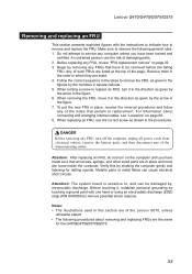
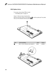
Lenovo G470/G475/G570/G575 Hardware Maintenance Manual 1030 Optical drive For access, remove these FRUs in the direction shown by arrow 2 3. 1 Step 1 Screw (quantity) M2.5 × 8 mm, flat-head, nylon-coated (1) Color Black Torque 2.0kgfcm 2 3 36 Removal steps of optical drive Remove the screw shown in the illustration 1, and then gently pull the optical drive out in order: •• "1010 Battery pack" on page 34 Figure 3.
Lenovo G470/G475/G570/G575 Hardware Maintenance Manual 1030 Optical drive For access, remove these FRUs in the direction shown by arrow 2 3. 1 Step 1 Screw (quantity) M2.5 × 8 mm, flat-head, nylon-coated (1) Color Black Torque 2.0kgfcm 2 3 36 Removal steps of optical drive Remove the screw shown in the illustration 1, and then gently pull the optical drive out in order: •• "1010 Battery pack" on page 34 Figure 3.
Hardware Maintenance Manual
Page 41
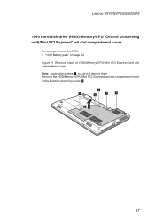
Remove the HDD/Memory/CPU/Mini PCI ExpressCard slot compartment cover in the direction shown by arrow 2. 1 1 1 1 1 2 37 Removal steps of HDD/Memory/CPU/Mini PCI ExpressCard slot compartment cover Note: Loosen the screws 1, but do not remove them. Lenovo G470/G475/G570/G575 1040 Hard disk drive (HDD)/Memory/CPU (Central processing unit)/Mini PCI ExpressCard slot compartment cover For access, remove this FRU: •• "1010 Battery pack" on page 34 Figure 4.
Remove the HDD/Memory/CPU/Mini PCI ExpressCard slot compartment cover in the direction shown by arrow 2. 1 1 1 1 1 2 37 Removal steps of HDD/Memory/CPU/Mini PCI ExpressCard slot compartment cover Note: Loosen the screws 1, but do not remove them. Lenovo G470/G475/G570/G575 1040 Hard disk drive (HDD)/Memory/CPU (Central processing unit)/Mini PCI ExpressCard slot compartment cover For access, remove this FRU: •• "1010 Battery pack" on page 34 Figure 4.

Hardware Maintenance Manual
Page 42
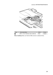
... in the direction shown by arrow 2. Improper handling can cause damages and permanent loss of Hard disk drive Remove two screws 1. Pull the HDD bracket in a metal frame 3. 1 1 2 38 Lenovo G470/G475/G570/G575 Hardware Maintenance Manual 1050 Hard disk drive For access, remove these FRUs in order: •• "1010 Battery pack...
... in the direction shown by arrow 2. Improper handling can cause damages and permanent loss of Hard disk drive Remove two screws 1. Pull the HDD bracket in a metal frame 3. 1 1 2 38 Lenovo G470/G475/G570/G575 Hardware Maintenance Manual 1050 Hard disk drive For access, remove these FRUs in order: •• "1010 Battery pack...
Hardware Maintenance Manual
Page 43
Lenovo G470/G475/G570/G575 3 Step 1 Screw (quantity) M2.0 × 4 mm, flat-head, nylon-coated (2) Color Black Torque 2.0kgfcm When installing: Make sure that the HDD connector is attached firmly. 39
Lenovo G470/G475/G570/G575 3 Step 1 Screw (quantity) M2.0 × 4 mm, flat-head, nylon-coated (2) Color Black Torque 2.0kgfcm When installing: Make sure that the HDD connector is attached firmly. 39

Hardware Maintenance Manual
Page 45
...; 3.2 mm, with spring, nylon-coated (4) Black Torque 2.0kgfcm 2.0kgfcm 41 Removal steps of fan assembly and heat sink assembly Note: Remove three screws 1 and four spring screws 2. Lenovo G470/G475/G570/G575 1070 Fan assembly and Heat Sink assembly For access, remove these FRUs in the direction shown by arrow 3. 1 1 2 2 2 1 2 3 When installing: Make sure...
...; 3.2 mm, with spring, nylon-coated (4) Black Torque 2.0kgfcm 2.0kgfcm 41 Removal steps of fan assembly and heat sink assembly Note: Remove three screws 1 and four spring screws 2. Lenovo G470/G475/G570/G575 1070 Fan assembly and Heat Sink assembly For access, remove these FRUs in the direction shown by arrow 3. 1 1 2 2 2 1 2 3 When installing: Make sure...

Hardware Maintenance Manual
Page 48
... of CPU Rotate the head of the screw in the direction shown by arrow 1 to release the lock, then remove the CPU in the direction shown by arrow 2. 1 a b 2 When installing: Place the CPU on page 41 Attention: CPU is extremely sensitive. Lenovo G470/G475/G570/G575 Hardware Maintenance Manual 1080 CPU For access...;• "1070 Fan assembly and Heat Sink assembly" on the CPU socket in the direction shown by arrow a , and then rotate the head of the screw in the direction shown by arrow b to secure the CPU. 44
... of CPU Rotate the head of the screw in the direction shown by arrow 1 to release the lock, then remove the CPU in the direction shown by arrow 2. 1 a b 2 When installing: Place the CPU on page 41 Attention: CPU is extremely sensitive. Lenovo G470/G475/G570/G575 Hardware Maintenance Manual 1080 CPU For access...;• "1070 Fan assembly and Heat Sink assembly" on the CPU socket in the direction shown by arrow a , and then rotate the head of the screw in the direction shown by arrow b to secure the CPU. 44
Hardware Maintenance Manual
Page 49
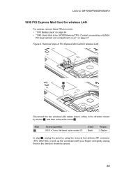
Lenovo G470/G475/G570/G575 1090 PCI Express Mini Card for wireless LAN 1 2 Disconnect the... two wireless LAN cables (black, white) in order: •• "1010 Battery pack" on page 34 •• "1040 Hard disk drive (HDD)/Memory/CPU (Central processing unit)/Mini PCI ExpressCard slot compartment cover " on page 37 Figure 9. Step 2 Screw...and gently unplug them in the direction shown by arrows 1, and then remove the screw 2. Removal steps of PCI Express Mini Card for wireless LAN For access, remove these FRUs in...
Lenovo G470/G475/G570/G575 1090 PCI Express Mini Card for wireless LAN 1 2 Disconnect the... two wireless LAN cables (black, white) in order: •• "1010 Battery pack" on page 34 •• "1040 Hard disk drive (HDD)/Memory/CPU (Central processing unit)/Mini PCI ExpressCard slot compartment cover " on page 37 Figure 9. Step 2 Screw...and gently unplug them in the direction shown by arrows 1, and then remove the screw 2. Removal steps of PCI Express Mini Card for wireless LAN For access, remove these FRUs in...

Hardware Maintenance Manual
Page 51
Removal steps of keyboard Remove the screws 1, 2 on page 37 Figure 10. Lenovo G470/G475/G570/G575 1100 Keyboard For access, remove these FRUs in order: •• "1010 Battery pack" on page 34 •• "1040 Hard disk drive (HDD)/Memory/CPU (Central processing unit)/Mini PCI ExpressCard slot compartment cover " on the bottom. 1 1 2 Step 1 2 Screw (quantity) M2.5 × 8 mm, flat-head, nylon-coated (2) M2.5 × 4 mm, flat-head, nylon-coated (1) Color Black Black Torque 2.0kgfcm 2.0kgfcm 47
Removal steps of keyboard Remove the screws 1, 2 on page 37 Figure 10. Lenovo G470/G475/G570/G575 1100 Keyboard For access, remove these FRUs in order: •• "1010 Battery pack" on page 34 •• "1040 Hard disk drive (HDD)/Memory/CPU (Central processing unit)/Mini PCI ExpressCard slot compartment cover " on the bottom. 1 1 2 Step 1 2 Screw (quantity) M2.5 × 8 mm, flat-head, nylon-coated (2) M2.5 × 4 mm, flat-head, nylon-coated (1) Color Black Black Torque 2.0kgfcm 2.0kgfcm 47
Hardware Maintenance Manual
Page 53
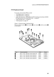
Removal steps of keyboard bezel Remove thirteen screws 1, two screws 2, two screws 3 and four screws 4 on page 47 Figure 11. Lenovo G470/G475/G570/G575 1110 Keyboard bezel For access, remove these FRUs in order: •• "1010 Battery pack" on page 34 ...8226;• "1050 Hard disk drive " on page 38 •• "1100 Keyboard" on the bottom. 11 1 1 1 1 3 3 1 4 4 1 4 1 4 1 1 2 2 1 1 Step 1 2 3 4 Screw (quantity) M2.5 × 8 mm, flat-head, nylon-coated (13) M2.0 × 5 mm, flat-head, nylon-coated (2) M2.0 × 3 mm, flat-head, nylon-coated (2) M2.0 ×...
Removal steps of keyboard bezel Remove thirteen screws 1, two screws 2, two screws 3 and four screws 4 on page 47 Figure 11. Lenovo G470/G475/G570/G575 1110 Keyboard bezel For access, remove these FRUs in order: •• "1010 Battery pack" on page 34 ...8226;• "1050 Hard disk drive " on page 38 •• "1100 Keyboard" on the bottom. 11 1 1 1 1 3 3 1 4 4 1 4 1 4 1 1 2 2 1 1 Step 1 2 3 4 Screw (quantity) M2.5 × 8 mm, flat-head, nylon-coated (13) M2.0 × 5 mm, flat-head, nylon-coated (2) M2.0 × 3 mm, flat-head, nylon-coated (2) M2.0 ×...

Hardware Maintenance Manual
Page 54
Removal steps of keyboard bezel (continued) Remove one screw 5 and detach three FPC connectors in the direction shown by arrows 6. 6 5 6 Step 5 Screw (quantity) M2.5 × 8 mm, flat-head, nylon-coated (1) Color Black Torque 2.0kgfcm When installing: Make sure that all the FPC connectors are attached firmly. 50 Lenovo G470/G475/G570/G575 Hardware Maintenance Manual Figure 11.
Removal steps of keyboard bezel (continued) Remove one screw 5 and detach three FPC connectors in the direction shown by arrows 6. 6 5 6 Step 5 Screw (quantity) M2.5 × 8 mm, flat-head, nylon-coated (1) Color Black Torque 2.0kgfcm When installing: Make sure that all the FPC connectors are attached firmly. 50 Lenovo G470/G475/G570/G575 Hardware Maintenance Manual Figure 11.
Hardware Maintenance Manual
Page 56
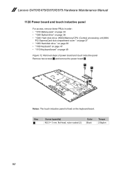
... remove the power board 2. 1 1 2 Notes: The touch inductive panel is fixed on page 49 Figure 12. Step 1 Screw (quantity) M2.0 × 3 mm, flat-head, nylon-coated (2) Color Black Torque 2.0kgfcm 52 Lenovo G470/G475/G570/G575 Hardware Maintenance Manual 1120 Power board and touch inductive panel For access, remove these FRUs in order...
... remove the power board 2. 1 1 2 Notes: The touch inductive panel is fixed on page 49 Figure 12. Step 1 Screw (quantity) M2.0 × 3 mm, flat-head, nylon-coated (2) Color Black Torque 2.0kgfcm 52 Lenovo G470/G475/G570/G575 Hardware Maintenance Manual 1120 Power board and touch inductive panel For access, remove these FRUs in order...

Hardware Maintenance Manual
Page 58
Step 2 Screw (quantity) M2.5 × 4 mm, flat-head, nylon-coated (5) Color Black Torque 2.0kgfcm 54 Lenovo G470/G475/G570/G575 Hardware Maintenance Manual Figure 13. Removal steps of system board (continued) Remove five screws 2 and detach a connector in the direction shown by arrow 3. 2 32 2 2 2 3 When installing: Make sure that the connector is attached firmly.
Step 2 Screw (quantity) M2.5 × 4 mm, flat-head, nylon-coated (5) Color Black Torque 2.0kgfcm 54 Lenovo G470/G475/G570/G575 Hardware Maintenance Manual Figure 13. Removal steps of system board (continued) Remove five screws 2 and detach a connector in the direction shown by arrow 3. 2 32 2 2 2 3 When installing: Make sure that the connector is attached firmly.
Hardware Maintenance Manual
Page 60
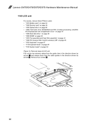
Removal steps of LCD unit Pull out the two antenna cables from the guide hole in the direction shown by arrows 2. Remove four screws 3. 1 1 56 Lenovo G470/G475/G570/G575 Hardware Maintenance Manual 1140 LCD unit For access, remove these FRUs in the direction shown by arrows 1 and release them from the cable guides...
Removal steps of LCD unit Pull out the two antenna cables from the guide hole in the direction shown by arrows 2. Remove four screws 3. 1 1 56 Lenovo G470/G475/G570/G575 Hardware Maintenance Manual 1140 LCD unit For access, remove these FRUs in the direction shown by arrows 1 and release them from the cable guides...

Hardware Maintenance Manual
Page 61
Step 3 Screw (quantity) M2.5 × 5 mm, flat-head, nylon-coated (4) Color Black Torque 2.0kgfcm 57 As you route the cables, make sure that they are not subjected to be damaged by the cable guides, or a wire to any tension. Tension could cause the cables to be broken. Removal steps of LCD unit (continued) 33 33 2 2 When installing: •• Route the antenna cables along the cable guides. Lenovo G470/G475/G570/G575 Figure 14.
Step 3 Screw (quantity) M2.5 × 5 mm, flat-head, nylon-coated (4) Color Black Torque 2.0kgfcm 57 As you route the cables, make sure that they are not subjected to be damaged by the cable guides, or a wire to any tension. Tension could cause the cables to be broken. Removal steps of LCD unit (continued) 33 33 2 2 When installing: •• Route the antenna cables along the cable guides. Lenovo G470/G475/G570/G575 Figure 14.
Hardware Maintenance Manual
Page 63
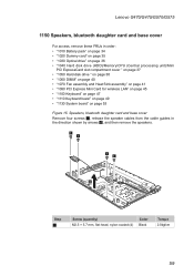
Speakers, bluetooth daughter card and base cover Remove four screws 1, release the speaker cables from the cable guides in order: •• "1010 Battery pack" on page 34 •• "1020 Dummy card" on page ...; "1100 Keyboard" on page 47 •• "1110 Keyboard bezel" on page 49 •• "1130 System board" on page 53 Figure 15. Lenovo G470/G475/G570/G575 1150 Speakers, bluetooth daughter card and base cover For access, remove these FRUs in the direction shown by arrows 2, and then remove the speakers...
Speakers, bluetooth daughter card and base cover Remove four screws 1, release the speaker cables from the cable guides in order: •• "1010 Battery pack" on page 34 •• "1020 Dummy card" on page ...; "1100 Keyboard" on page 47 •• "1110 Keyboard bezel" on page 49 •• "1130 System board" on page 53 Figure 15. Lenovo G470/G475/G570/G575 1150 Speakers, bluetooth daughter card and base cover For access, remove these FRUs in the direction shown by arrows 2, and then remove the speakers...

