Hardware Maintenance Manual
Page 5
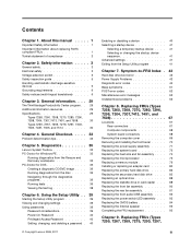
... translations) . . . . . 6 Chapter 3. Replacing FRUs (Types 7259, 7267, 7269, 7279, 7290, 7297, iii Diagnostics 35 Lenovo System Toolbox 35 PC-Doctor for Windows PE 35 Running diagnostics from the Rescue and Recovery workspace 35 PC-Doctor for DOS 36 Creating a ... power supply assembly . . . . . 71 Replacing the system board 72 Replacing the heat sink and fan assembly . . . . 74 Replacing the microprocessor 75 Replacing a memory module 79 Installing or replacing an adapter card . . . . . 80 Replacing the primary hard disk drive. . . . . . 82 Replacing the secondary hard disk drive...
... translations) . . . . . 6 Chapter 3. Replacing FRUs (Types 7259, 7267, 7269, 7279, 7290, 7297, iii Diagnostics 35 Lenovo System Toolbox 35 PC-Doctor for Windows PE 35 Running diagnostics from the Rescue and Recovery workspace 35 PC-Doctor for DOS 36 Creating a ... power supply assembly . . . . . 71 Replacing the system board 72 Replacing the heat sink and fan assembly . . . . 74 Replacing the microprocessor 75 Replacing a memory module 79 Installing or replacing an adapter card . . . . . 80 Replacing the primary hard disk drive. . . . . . 82 Replacing the secondary hard disk drive...
Hardware Maintenance Manual
Page 6
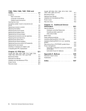
... 97 Locations 97 Rear connectors 97 Computer components 98 System board connectors 98 Opening the cover 99 Accessing system board components and drives 100 Replacing a memory module 100 Replacing the battery 101 Replacing the power supply 102 Replacing the system board 104 Replacing the microprocessor 107 Replacing the heat sink and...
... 97 Locations 97 Rear connectors 97 Computer components 98 System board connectors 98 Opening the cover 99 Accessing system board components and drives 100 Replacing a memory module 100 Replacing the battery 101 Replacing the power supply 102 Replacing the system board 104 Replacing the microprocessor 107 Replacing the heat sink and...
Hardware Maintenance Manual
Page 50
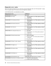
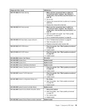
... log file 2. Reboot the system 2. System board 1. See "Flash update procedures" on page 521 3. See "Flash update procedures" on page 521 2. Flash the system. Run memory test 4. System board 1. Adapter card 3. System board 1. Flash the system. System board 1. System board 1. Press F3 to reset the log file 44 ThinkCentre Hardware Maintenance...
... log file 2. Reboot the system 2. System board 1. See "Flash update procedures" on page 521 3. See "Flash update procedures" on page 521 2. Flash the system. Run memory test 4. System board 1. Adapter card 3. System board 1. Flash the system. System board 1. System board 1. Press F3 to reset the log file 44 ThinkCentre Hardware Maintenance...
Hardware Maintenance Manual
Page 51
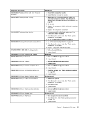
... update procedures" on page 521 2. See "Flash update procedures" on page 521 3. System board 1. See "Flash update procedures" on page 39 2. Reboot the system 2. Run memory test 4. Flash the system and re-test 3. System board 1. Flash the system. System board System board 1. Re-run test 3. Make sure the component that is...
... update procedures" on page 521 2. See "Flash update procedures" on page 521 3. System board 1. See "Flash update procedures" on page 39 2. Reboot the system 2. Run memory test 4. Flash the system and re-test 3. System board 1. Flash the system. System board System board 1. Re-run test 3. Make sure the component that is...
Hardware Maintenance Manual
Page 57
... board 1. See "Flash update procedures" on page 521 3. System board System board 1. System board 1. Go to -FRU Index 51 System board 1. Flash the system. Run memory test 4. See "Flash update procedures" on page 521 3. Flash the system and re-test. See "Flash update procedures" on page 521 3. Flash the system. Replace...
... board 1. See "Flash update procedures" on page 521 3. System board System board 1. System board 1. Go to -FRU Index 51 System board 1. Flash the system. Run memory test 4. See "Flash update procedures" on page 521 3. Flash the system and re-test. See "Flash update procedures" on page 521 3. Flash the system. Replace...

Hardware Maintenance Manual
Page 66
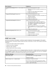
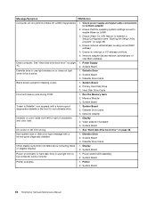
...Security Test Passed 185-XXX-XXX Asset Security failure 185-278-XXX Asset Security Chassis Intrusion 201-000-XXX System Memory Test Passed 201-XXX-XXX System Memory error 202-000-XXX System Cache Test Passed 202-XXX-XXX System Cache error 206-000-XXX Diskette Drive ... error FRU/Action 1. System board No action 1. Reseat the hard disk drive cable 4. See "Undetermined problems" on page 521 3. Check fans 2. Replace the memory module called out by the test 2. CD-ROM drive 4. Hard Disk drive (IDE) 5. Replace component under function test 1. Assure Asset Security Enabled 2. Diskette ...
...Security Test Passed 185-XXX-XXX Asset Security failure 185-278-XXX Asset Security Chassis Intrusion 201-000-XXX System Memory Test Passed 201-XXX-XXX System Memory error 202-000-XXX System Cache Test Passed 202-XXX-XXX System Cache error 206-000-XXX Diskette Drive ... error FRU/Action 1. System board No action 1. Reseat the hard disk drive cable 4. See "Undetermined problems" on page 521 3. Check fans 2. Replace the memory module called out by the test 2. CD-ROM drive 4. Hard Disk drive (IDE) 5. Replace component under function test 1. Assure Asset Security Enabled 2. Diskette ...
Hardware Maintenance Manual
Page 68
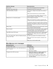
...called the Power-On Self-Test, or POST. Perform the following actions in the connector(s). 2. Replace the system board. Replace the memory module(s). 3. This series of CMOS is properly connected to the computer. 2. defaults loaded Replace the battery. The computer loads the ... (if present). 3. Perform a Boot block recovery. Perform the following actions in order. 1. Make sure the keyboard is incorrect. Make sure the memory module(s) are properly seated in order. 1. CMOS checksum error - Beep Symptom 1 long and 2 short beeps Monitor or video adapter card error 1...
...called the Power-On Self-Test, or POST. Perform the following actions in the connector(s). 2. Replace the system board. Replace the memory module(s). 3. This series of CMOS is properly connected to the computer. 2. defaults loaded Replace the battery. The computer loads the ... (if present). 3. Perform a Boot block recovery. Perform the following actions in order. 1. Make sure the keyboard is incorrect. Make sure the memory module(s) are properly seated in order. 1. CMOS checksum error - Beep Symptom 1 long and 2 short beeps Monitor or video adapter card error 1...
Hardware Maintenance Manual
Page 69
... POST screen Error: Non-System disk or disk error Replace and press any key when ready Description/Action nnnn is the running speed of the memory error. If no keys are installed, make sure the hard disk drive selection in Setup is enabled for RPL 3. To purposely configure the computer ... the user to HALT ON ALL, BUT KEYBOARD. The BIOS was unable to the computer and that no hard disk drives are held pressed during memory testing, additional information appears. Make sure you have bootable media. Computer will not power-off. Ensure that network adapter is set the error halt ...
... POST screen Error: Non-System disk or disk error Replace and press any key when ready Description/Action nnnn is the running speed of the memory error. If no keys are installed, make sure the hard disk drive selection in Setup is enabled for RPL 3. To purposely configure the computer ... the user to HALT ON ALL, BUT KEYBOARD. The BIOS was unable to the computer and that no hard disk drives are held pressed during memory testing, additional information appears. Make sure you have bootable media. Computer will not power-off. Ensure that network adapter is set the error halt ...
Hardware Maintenance Manual
Page 70
Ensure network administrator is active. 1. Diskette Drive 2. Primary Hard Disk Drive 3. Hard Disk Drive Cable Incorrect memory size during POST 1. System Board 2. See "Hard disk drive boot error" on page 43. 1. Diskette Drive 2. Display 2. Ensure Wake On ... boot error" on page 43. Power Supply 2. System Board Diskette drive in the first 3.5-inch diskette drive. 1. System Board 2. Run the Memory tests 2. Memory Module 3. Diskette Drive Cable 3. Network Adapter Intensity or color varies from left to right of new MAC address) Dead computer. System Board No ...
Ensure network administrator is active. 1. Diskette Drive 2. Primary Hard Disk Drive 3. Hard Disk Drive Cable Incorrect memory size during POST 1. System Board 2. See "Hard disk drive boot error" on page 43. 1. Diskette Drive 2. Display 2. Ensure Wake On ... boot error" on page 43. Power Supply 2. System Board Diskette drive in the first 3.5-inch diskette drive. 1. System Board 2. Run the Memory tests 2. Memory Module 3. Diskette Drive Cable 3. Network Adapter Intensity or color varies from left to right of new MAC address) Dead computer. System Board No ...
Hardware Maintenance Manual
Page 71
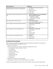
... disk drive, make sure that the hard disk drive is jumpered as a slave. 1. External Cache RAM g. First device - External Device Self-Test OK? 2. External Device 3. Memory modules d. Any adapters c. Symptom-to re-test the system. 4. network b. If all keys on the computer to -FRU Index 65 Diskette Drive Cable 4. Check the... diskette drive 1. Diskette Drive 3. System Board Some or all devices and adapters have been removed, and the problem continues, replace the system board. Extended video memory e. External Cache f. Chapter 7.
... disk drive, make sure that the hard disk drive is jumpered as a slave. 1. External Cache RAM g. First device - External Device Self-Test OK? 2. External Device 3. Memory modules d. Any adapters c. Symptom-to re-test the system. 4. network b. If all keys on the computer to -FRU Index 65 Diskette Drive Cable 4. Check the... diskette drive 1. Diskette Drive 3. System Board Some or all devices and adapters have been removed, and the problem continues, replace the system board. Extended video memory e. External Cache f. Chapter 7.

Hardware Maintenance Manual
Page 74
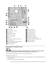
... Serial port (some models) Computer components The following illustration will help you locate the major FRUs in the computer. 1 Heat sink, and fan assembly 2 Microprocessor 3 Memory 4 Optical drive 5 Diskette drive 6 Power switch / LED assembly 7 Internal speaker 8 Front audio / USB assembly 9 Hard disk drive 10 System board 11 Rear system fan 12...
... Serial port (some models) Computer components The following illustration will help you locate the major FRUs in the computer. 1 Heat sink, and fan assembly 2 Microprocessor 3 Memory 4 Optical drive 5 Diskette drive 6 Power switch / LED assembly 7 Internal speaker 8 Front audio / USB assembly 9 Hard disk drive 10 System board 11 Rear system fan 12...
Hardware Maintenance Manual
Page 75
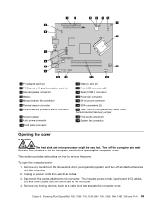
To remove the computer cover: 1. 1 Microprocessor 2 Microprocessor fan connector 3 Memory slots (2) 4 Thermal sensor connector 5 Diskette drive connector 6 24-pin power connector 7 Battery 8 Cover presence (Intrusion) switch connector 9 SATA connectors (4) 10 Clear CMOS (Complementary Metal Oxide ...
To remove the computer cover: 1. 1 Microprocessor 2 Microprocessor fan connector 3 Memory slots (2) 4 Thermal sensor connector 5 Diskette drive connector 6 24-pin power connector 7 Battery 8 Cover presence (Intrusion) switch connector 9 SATA connectors (4) 10 Clear CMOS (Complementary Metal Oxide ...

Hardware Maintenance Manual
Page 80
... sink and fan assembly" on the system board. Turn off the computer and wait three to five minutes to the system board. Remove the memory modules from the failing system board and install them in the new system board. Lower the microprocessor retainer and then lower the lever to the...type at "System board connectors" on the new system board. 12. To obtain a copy of the ThinkCentre Safety and Warranty Guide, go to: http://www.lenovo.com/support This section provides instructions on page 75. 14. Connect the power and signal cables to replace the heat sink and fan assembly. Make...
... sink and fan assembly" on the system board. Turn off the computer and wait three to five minutes to the system board. Remove the memory modules from the failing system board and install them in the new system board. Lower the microprocessor retainer and then lower the lever to the...type at "System board connectors" on the new system board. 12. To obtain a copy of the ThinkCentre Safety and Warranty Guide, go to: http://www.lenovo.com/support This section provides instructions on page 75. 14. Connect the power and signal cables to replace the heat sink and fan assembly. Make...
Hardware Maintenance Manual
Page 85
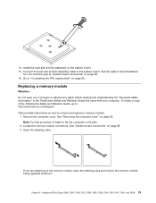
... clips and remove the memory module being replaced as shown. Install the heat sink and fan assembly on page 68. 3. See "System board connectors" on the system board. 15. To obtain a copy of the ThinkCentre Safety and Warranty Guide, go to: http://www.lenovo.com/support This provides... instructions on how to the system board. Locate the memory module connectors. If you are replacing an old memory module, open your computer or attempt any repair before reading and understanding the "...
... clips and remove the memory module being replaced as shown. Install the heat sink and fan assembly on page 68. 3. See "System board connectors" on the system board. 15. To obtain a copy of the ThinkCentre Safety and Warranty Guide, go to: http://www.lenovo.com/support This provides... instructions on how to the system board. Locate the memory module connectors. If you are replacing an old memory module, open your computer or attempt any repair before reading and understanding the "...

Hardware Maintenance Manual
Page 86
...installing an adapter card, remove the appropriate slot cover. At the rear of the ThinkCentre Safety and Warranty Guide, go to: http://www.lenovo.com/support This section provides instructions on how to "Completing the FRU replacement" on the system board. To obtain a copy of the ...before reading and understanding the "Important safety information" in the ThinkCentre Safety and Warranty Guide that the notch 1 on the memory module aligns correctly with your computer. Installing or replacing an adapter card Attention Do not open the adapter latch 2 . 4. Position the new...
...installing an adapter card, remove the appropriate slot cover. At the rear of the ThinkCentre Safety and Warranty Guide, go to: http://www.lenovo.com/support This section provides instructions on how to "Completing the FRU replacement" on the system board. To obtain a copy of the ...before reading and understanding the "Important safety information" in the ThinkCentre Safety and Warranty Guide that the notch 1 on the memory module aligns correctly with your computer. Installing or replacing an adapter card Attention Do not open the adapter latch 2 . 4. Position the new...

Hardware Maintenance Manual
Page 104
6 Parallel port 7 VGA monitor connector 13 PCI Express x16 graphics adapter card slot 14 PCI adapter card slot Computer components The following illustration will help you locate the major FRUs in the computer. 1 Hard disk drive 2 Microprocessor, heat sink and fan assembly 3 Internal speaker (some models) 4 Optical drive 5 Memory slots (2) 6 Power supply assembly System board connectors This illustration is to help locate the various system board connectors. 98 ThinkCentre Hardware Maintenance Manual
6 Parallel port 7 VGA monitor connector 13 PCI Express x16 graphics adapter card slot 14 PCI adapter card slot Computer components The following illustration will help you locate the major FRUs in the computer. 1 Hard disk drive 2 Microprocessor, heat sink and fan assembly 3 Internal speaker (some models) 4 Optical drive 5 Memory slots (2) 6 Power supply assembly System board connectors This illustration is to help locate the various system board connectors. 98 ThinkCentre Hardware Maintenance Manual
Hardware Maintenance Manual
Page 105
... slot 3 Internal speaker connector 4 Battery 5 Microprocessor fan connector 6 Thermal sensor connector 7 Cover presence (Intrusion) switch connector 8 Microprocessor 9 4-pin power connector 10 Front panel connector 11 Memory slots (2) 12 Front USB connectors (2) 13 Serial (COM 2) connector 14 Power fan connector 15 24-pin power connector 16 SATA connectors (2) 17 Clear CMOS (Complementary...
... slot 3 Internal speaker connector 4 Battery 5 Microprocessor fan connector 6 Thermal sensor connector 7 Cover presence (Intrusion) switch connector 8 Microprocessor 9 4-pin power connector 10 Front panel connector 11 Memory slots (2) 12 Front USB connectors (2) 13 Serial (COM 2) connector 14 Power fan connector 15 24-pin power connector 16 SATA connectors (2) 17 Clear CMOS (Complementary...

Hardware Maintenance Manual
Page 106
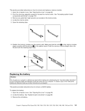
... Safety and Warranty Guide that you might need to pivot the drive bay assembly upward and remove the hard disk drive to :http://www.lenovo.com/support 100 ThinkCentre Hardware Maintenance Manual See "Opening the cover" on the sides of the ThinkCentre Safety and Warranty Guide, go to ...access the internal components. 3. On some models, you disconnect from the drives or the system board. Replacing a memory module Attention Do not open . To obtain a copy of the computer and pivot the computer cover upward to open your computer or attempt any cables...
... Safety and Warranty Guide that you might need to pivot the drive bay assembly upward and remove the hard disk drive to :http://www.lenovo.com/support 100 ThinkCentre Hardware Maintenance Manual See "Opening the cover" on the sides of the ThinkCentre Safety and Warranty Guide, go to ...access the internal components. 3. On some models, you disconnect from the drives or the system board. Replacing a memory module Attention Do not open . To obtain a copy of the computer and pivot the computer cover upward to open your computer or attempt any cables...
Hardware Maintenance Manual
Page 107
...correctly with your access to remove a CMOS battery. Pivot the drive bay assembly upward to remove and replace a memory module. 1. Locate the memory slots. 5. Push the memory module straight down into the slot until the retaining clips close. Open the computer cover. Open the retaining clips.... 6. To obtain a copy of the ThinkCentre Safety and Warranty Guide, go to:http://www.lenovo.com/support This section provides instructions how to the memory slots. 4. Remove the old battery. Locate the battery. Make sure that might prevent your computer. Chapter 9....
...correctly with your access to remove a CMOS battery. Pivot the drive bay assembly upward to remove and replace a memory module. 1. Locate the memory slots. 5. Push the memory module straight down into the slot until the retaining clips close. Open the computer cover. Open the retaining clips.... 6. To obtain a copy of the ThinkCentre Safety and Warranty Guide, go to:http://www.lenovo.com/support This section provides instructions how to the memory slots. 4. Remove the old battery. Locate the battery. Make sure that might prevent your computer. Chapter 9....

Hardware Maintenance Manual
Page 110
...Guide that came with your computer. This section provides instructions on the new system board. Remove the memory modules from the failing system board. Go to :http://www.lenovo.com/support CAUTION: The heat sink and microprocessor might be lifted out of the ThinkCentre Safety and ...page 118. See "Installing or replacing an adapter card" on page 98. 4. See "System board connectors" on page 116. 6. See "Replacing a memory module" on page 100. 8. To obtain a copy of the chassis. 104 ThinkCentre Hardware Maintenance Manual Pivot the drive-bay assembly upward to gain easier...
...Guide that came with your computer. This section provides instructions on the new system board. Remove the memory modules from the failing system board. Go to :http://www.lenovo.com/support CAUTION: The heat sink and microprocessor might be lifted out of the ThinkCentre Safety and ...page 118. See "Installing or replacing an adapter card" on page 98. 4. See "System board connectors" on page 116. 6. See "Replacing a memory module" on page 100. 8. To obtain a copy of the chassis. 104 ThinkCentre Hardware Maintenance Manual Pivot the drive-bay assembly upward to gain easier...


