LG T710BH Support and Manuals
Get Help and Manuals for this LG item

Most Recent LG T710BH Questions

I Need The Driver For Monitor T710 Bhk.
(Posted by nkhavas 12 years ago)
Popular LG T710BH Manual Pages
Service Manual - Page 1
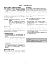
CAUTION
BEFORE SERVICING THE UNIT, READ THE SAFETY PRECAUTIONS IN THIS MANUAL. MENU
SELECT Brightview Website:http://biz.LGservice.com E-mail:http://www.LGEservice.com/techsup.html
COLOR MONITOR SERVICE MANUAL
CHASSIS NO. : CA-119
FACTORY MODEL: T710BH
MODEL:
T710B (T710BH-EL)
T710BH (T710BH-HL)
T710SH (T710BH-SL)
*( ) ID LABEL Model No.
Service Manual - Page 3
... the CDT anode cap.
• Set the brightness control to avoid damage and scratching during service operation. The high voltage meter should be taken while servicing this color monitor which must be taken to maximum point at the factory recommended level; These parts are equipped with the manufacturer's specified parts to remove all of the following...
Service Manual - Page 5
... Screen
Display (OSD) menu.
3. Press the buttons to adjust the settings and then the
MENU button to select brightview function. (TEXT/PHOTO/MOVIE...without entering
100
the On Screen Display (OSD)
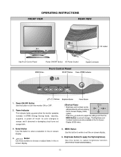
system. OPERATING INSTRUCTIONS
FRONT VIEW
REAR VIEW
MENU
SELECT Brightview
ID Label
See Front Control... the monitor ON or OFF.
2.
Power Indicator This indicator lights up green when the...
Service Manual - Page 7
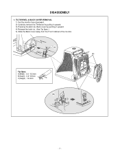
... B(Depth) : 0.6~0.9mm C(Height) : 12.0mm
C
Tip AB
(b)
1
3
3
2 2
-7- DISASSEMBLY
1. TILT/SWIVEL & BACK COVER REMOVAL 1) Set the monitor face downward. 2) Carefully remove the Tilt/Swivel by pulling it upward. 3) Pressing the latch (b), Back cover by pushing it upward. 4) Release the latch (c). (See Tip Spec.) 5) Slide the Back Cover away from the Front Cabinet of the...
Service Manual - Page 9
...This circuit is stored in itself. 5) User can adjust screen condition by changing DC level of power input line flowing into the monitor and/or some noise generated in accordance ...IC402).
6. And Brightness circuit is the secondary voltage of H and V sync. 3) The Micom sets operating mode and offers the
controlled data. (H-size, H-position, V-size, ... Horizontal and Vertical ...
Service Manual - Page 11
.... -
Install the cable for adjustment such as arrow keys to max position.
1. Set external Brightness...Signal Generator. (eg. AUTOMATIC AND MANUAL DEGAUSSING The degaussing coil is mounted around...Set the White Balance Meter. 2) Press the DEGAUSS on the OSD menu for T710BH on the monitor. ADJUSTMENT
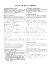
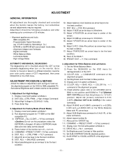
GENERAL INFORMATION
All adjustment are thoroughly checked and corrected when the monitor...
Service Manual - Page 12
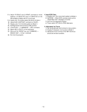
... command to 50±2FL . 19) Display color 15,0 full white patten at Mode 4. 20) Set Brightness and Contrast to Max position. 21) COLOR ADJ. → LUMINANCE → ABL command. 22...24) Exit from the alignment program. 4) Power switch OFF/ON for Focus. 1) Set the Brightness and Contrast to 32±1FL of monitor. 3) Exit from the program.
4. Input EDID Data. 1) Display color 15,0 cross...
Service Manual - Page 17

...
UNBALANCED OF H-LIN. YES
CHECK Q711~Q716?
CHECK IC401 PIN 5, 6, 7 ? YES
CHECK L703?
YES
TROUBLE IN C722, C723, C726, C729
NO
TROUBLE IN
IC401 (MICOM)
NO
TROUBLE IN
Q711 ~ Q716
NO
TROUBLE IN
L703
Cs SIGNAL TABLE
HORIZONTAL FREQUENCY(fH)
Cs1
Cs2
Cs3
30K ~ 33.9K
L
L
L
34K ~ 38.9K
L
H
H
39K ~ 43.9K H
L
H
44K ~ 48...
Service Manual - Page 18

6.
NO VERTICAL DEFLECTION
NO V-DEFLECTION (ONE HORIZONTAL LINE)
CHECK IC601 PIN 2
(13V+)? YES
NO
TROUBLE IN
D610 13V+ LINE
CHECK IC701 PIN 23?
3V
YES
NO
TROUBLE IN
IC701
TROUBLE IN IC601, V-CIRCUIT
- 18 -
Service Manual - Page 19

...
WAVEFORM? NO OSD
7. H+V 5V
YES
CHECK
NO
IC301 PIN 13, 14, 15 ? Pin 10 Pin 5
5V YES
CHECK
IC301 PIN 12
NO
WAVEFORM ? H+V 5V
YES
TROUBLE IN OSD PERIPHERAL CIRCUIT
TROUBLE IN 5V LINE
TROUBLE IN IC601 PIN1 (V-FBP), T701 40V LINE (H-FBP...
Service Manual - Page 20

TROUBLE IN DPM
OFF MODE FAILURE
(NO OFF MODE.)
CHECK IC401 (MICOM) PIN 30, 31 (H/V INPUT)
SIGNAL?
YES H/V ...0V)
CHECK
B+ LINE
NO
(6.3V,13V+, 105V) ? 8.
CHECK PC, (PC IS NOT GOING INTO DPM OFF MODE)
TROUBLE IN X401
TROUBLE IN IC401 (MICOM)
TROUBLE IN Q941, Q942, Q951, Q952,
YES TROUBLE IN PC
Mode Item NORMAL STAND-BY SUSPEND OFF
DPM TABLE
DPMF H L L L
DPMS H H H L
LED GREEN AMBER...
Service Manual - Page 21

YES
CHECK RL901? YES
TROUBLE IN TH901, DEGAUSSING COIL
NO NO NO NO
TROUBLE IN IC401 (MICOM)
TROUBLE IN Q953
TROUBLE IN P902
TROUBLE IN RL901
- 21 -
9. NO DEGAUSSING
NO DEGAUSSING
(DEGAUSS ON THE OSD MENU MUST BE PRESSED.)
CHECK IC401 PIN 1
(0V)? YES
CHECK Q953 COLLECTOR (15V) VOLTAGE? DC 15V
YES
CHECK P902 ?
Service Manual - Page 22

10. YES
TROUBLE IN P501, TILT COIL
NO
TROUBLE IN
IC401 (MICOM)
NO
TROUBLE IN
15V LINE, 6.3V LINE
NO
TROUBLE IN
Q501~Q503
- 22 - YES
CHECK Q503 EMITTER
VOLTAGE ?
YES
CHECK 13V LINE AND 6.3V LINE ?
NO TILT (NO ROTATION )
NO TILT (NO ROTATION)
CHECK IC401 PIN21 WAVE FORM ?
Service Manual - Page 24

...), M41QEE903X 01NHUD LG-PHILIPS 85KHZ 29.1MM FLAT TCO -For Northern hemishere(T710BH-HL), (T710BH-SL) BACK COVER ASSEMBLY, E710BH 046 EQ54(8C358) -(T710BH-EL), (T710BH-HL) BACK COVER ASSEMBLY "T710 C046 320T,EQ54(8C358) -(T710BH-SL) TILT SWIVEL ASSEMBLY, E710BH T066 B60 HIPS SCREW ASSEMBLY, TAPTITE P TYPE D5.0 L25.0 MSWR/FZMY . EXPLODED VIEW PARTS LIST
Ref...
Service Manual - Page 25

...5 0.0047U 100V J POLY NI TP5 0.1UF 50V Z F TR
*S *AL LOC. DESCRIPTION / SPECIFICATION MKT 100V 104JTR PHS26104 47UF SHL,SD 50V M FM5 TP 5 820P 50V K B TS 0.01U ... - NO. NO. REPLACEMENT PARTS LIST
CAUTION: BEFORE REPLACING ANY OF THESE COMPONENTS, READ CAREFULLY THE SAFETY PRECAUTIONS IN THIS MANUAL.
* NOTE : S SAFETY Mark AL ALTERNATIVE PARTS
*S *AL LOC. PART NO. CAPACITORS
DATE: 2003...
LG T710BH Reviews
We have not received any reviews for LG yet.