User Guide
Page 3
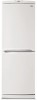
PARTS IDENTIFICATION Freezer Temperature _ Control Removable Glass Shelf(2 or 3) Lam Multi-air Flow Fresh Meat Kee (Optional) Temperature Control Used to change. -5- The shape of refrigerator is a basic model. Compartment Plinth or 2) Door Basket (3 or 5) Utility Comer (movable) Bottle Holder -2J_ Bottle Door Basket Screw NOTE : This is subject to keep fruits and vegetables, etc. fresh and crisp.
PARTS IDENTIFICATION Freezer Temperature _ Control Removable Glass Shelf(2 or 3) Lam Multi-air Flow Fresh Meat Kee (Optional) Temperature Control Used to change. -5- The shape of refrigerator is a basic model. Compartment Plinth or 2) Door Basket (3 or 5) Utility Comer (movable) Bottle Holder -2J_ Bottle Door Basket Screw NOTE : This is subject to keep fruits and vegetables, etc. fresh and crisp.
User Guide
Page 5
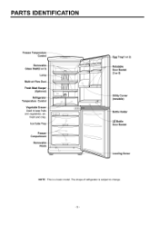
...remove from the Door Foam Assy, F. Figure 7 • Refrigerator Door 1) Loosen hexagonal bolts fixing the center hinge(Hinge,C) to the body to remove the freezer door only. Lower Hinge 2 DOOR SWITCH 1) Loosen four screws in upper part and disconnect top cover. 2) Disconnect Lead Wire from switch. 3)... Disengage hook behind the switch by turning. Figure 10 e,C Figure 8 2) Pull out the Door Gasket...
...remove from the Door Foam Assy, F. Figure 7 • Refrigerator Door 1) Loosen hexagonal bolts fixing the center hinge(Hinge,C) to the body to remove the freezer door only. Lower Hinge 2 DOOR SWITCH 1) Loosen four screws in upper part and disconnect top cover. 2) Disconnect Lead Wire from switch. 3)... Disengage hook behind the switch by turning. Figure 10 e,C Figure 8 2) Pull out the Door Gasket...
User Guide
Page 9
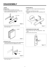
TROUBLESHOOTING (Mechanical Part) 1 COMPRESSOR AND ELECTRIC COMPONENTS SPoouwrecer . Remove the PTC]_ Starter from the Compressor and measure the voltage between Terminal C of Compressor and Terminals 5 or 6 of two terminals in PTC- YES _ OLP disconnected? Check the resistance of PTC. (Rating Voltage _+10%)? PTC-Starter. _I Sthaertcekr. I RPTepCl-aSctearter. YES Csthaertcinkg state. ... in O_K_ NO -11 - isn't Check the resistance of YES NO _- the resistance of Motor Compressor. _ among M-C, S-C and M-S in the range of Rating Voltage -+10% below.
TROUBLESHOOTING (Mechanical Part) 1 COMPRESSOR AND ELECTRIC COMPONENTS SPoouwrecer . Remove the PTC]_ Starter from the Compressor and measure the voltage between Terminal C of Compressor and Terminals 5 or 6 of two terminals in PTC- YES _ OLP disconnected? Check the resistance of PTC. (Rating Voltage _+10%)? PTC-Starter. _I Sthaertcekr. I RPTepCl-aSctearter. YES Csthaertcinkg state. ... in O_K_ NO -11 - isn't Check the resistance of YES NO _- the resistance of Motor Compressor. _ among M-C, S-C and M-S in the range of Rating Voltage -+10% below.
User Guide
Page 11
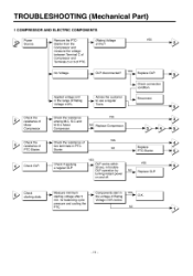
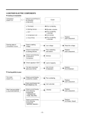
... impossible COMPONENTS Compressor doesn't run . [__ Check current flowing in sub-coil of motor Compressor. 3 ANOTHER ELECTRIC • Cooling is poor. ] Check a starting devices. Circuit Parts Cause. _- Poor contacting. Replace each component. a. Thermistor b. Compressor coil e. Replace each component. t Check current flowing in SWITCH, DOOR. OLP d. Running state of the following components...
... impossible COMPONENTS Compressor doesn't run . [__ Check current flowing in sub-coil of motor Compressor. 3 ANOTHER ELECTRIC • Cooling is poor. ] Check a starting devices. Circuit Parts Cause. _- Poor contacting. Replace each component. a. Thermistor b. Compressor coil e. Replace each component. t Check current flowing in SWITCH, DOOR. OLP d. Running state of the following components...
User Guide
Page 12
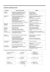
...Don't open the door too often and close it firmly. • Set the control to mid-position. • Place foods in high temperature section. (Front Part) • Set the control to "mid-position". • Set the control to solve the complaint. This occurrence is low, wire newly. • Place... and direct rays. • is the ambient temperature high or the room door closed up the gap. Dew or ice forms in the Freezer. Defrosting is poor. Replace the Components of surroumcling air are frozen. Check Refrigerating Cycle. Replace the Damper Control Cooling ability is poor.
...Don't open the door too often and close it firmly. • Set the control to mid-position. • Place foods in high temperature section. (Front Part) • Set the control to "mid-position". • Set the control to solve the complaint. This occurrence is low, wire newly. • Place... and direct rays. • is the ambient temperature high or the room door closed up the gap. Dew or ice forms in the Freezer. Defrosting is poor. Replace the Components of surroumcling air are frozen. Check Refrigerating Cycle. Replace the Damper Control Cooling ability is poor.
User Guide
Page 13
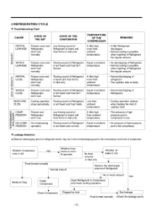
...8226; The pressure of high pressure part in compressor is low. • No pressure of high pressure part in the compressor. • Leakage Detection • Observe discharging point of refrigerant which may be in the oil discharging part in the compressor and hole of ...dust. Frost formed normally 7¸ _'1 Gas leakage. (Check the leakage point) -15- Freezer room and Refrigerator don't cool. Flowing sound of Refrigerant is heard and frost forms in inlet only. 5 REFRIGERATING CYCLE • Troubleshooting Chart CAUSE STATE OF THE SET STATE OF THE EVAPORATOR PARTIAL LEAKAGE ...
...8226; The pressure of high pressure part in compressor is low. • No pressure of high pressure part in the compressor. • Leakage Detection • Observe discharging point of refrigerant which may be in the oil discharging part in the compressor and hole of ...dust. Frost formed normally 7¸ _'1 Gas leakage. (Check the leakage point) -15- Freezer room and Refrigerator don't cool. Flowing sound of Refrigerant is heard and frost forms in inlet only. 5 REFRIGERATING CYCLE • Troubleshooting Chart CAUSE STATE OF THE SET STATE OF THE EVAPORATOR PARTIAL LEAKAGE ...
User Guide
Page 14
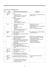
...CONTENTS AND SPECIFICATIONS REMARKS (1) H 30 • Chemical Ingredients Ag: 30%, Cu: 27%, Zn: 23%, Cd: 20% • Brazing Temperature: 710~840°C (2) Bcup-2 • Chemical Ingredients Cu: About 93% P: 6.8~7.5% The rest: within 30min. after 5 min.... part. (1) The pressure of dry air must be more han 12~16kg/cm 2 (2) Temperature must be more than -20- -70°C. (3) Keep the pressure at the temperature of the cycle inside is 10 ... says no vacuum leakage state. (3) Vacuum degree of Refrigerating Cycle NO. • General Control of vacuum pump must be 0.05 Torr.
...CONTENTS AND SPECIFICATIONS REMARKS (1) H 30 • Chemical Ingredients Ag: 30%, Cu: 27%, Zn: 23%, Cd: 20% • Brazing Temperature: 710~840°C (2) Bcup-2 • Chemical Ingredients Cu: About 93% P: 6.8~7.5% The rest: within 30min. after 5 min.... part. (1) The pressure of dry air must be more han 12~16kg/cm 2 (2) Temperature must be more than -20- -70°C. (3) Keep the pressure at the temperature of the cycle inside is 10 ... says no vacuum leakage state. (3) Vacuum degree of Refrigerating Cycle NO. • General Control of vacuum pump must be 0.05 Torr.
User Guide
Page 16
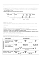
... MOVING) r- FAN J= ON WHEN RETURNING TO NORMAL STATE FROM TEST MODE All Elec. FAN =" ON 4) DOOR OPENING ALARM (1) When the REFRIGERATOR DOOR is opened and won't be closed during DEFROSTING, end the operation of DEFROSTING with "DING- DONG-"(See the BUZZER OPERATION CHECK) 6) DEFROSTING... power is on, (3) If DEFROST SENSOR is over 7°C during ALARM, it is released. DEFROSTING "_ HEATER ON after 7 min. -18- Parts OFF after 10 sec. after 0.5 sec. FAN ON POWER ON DEFROSTING _ HEATER ON after 0.5 sec. COMP _'_ ON after 2 hours' operation of the defrosting ...
... MOVING) r- FAN J= ON WHEN RETURNING TO NORMAL STATE FROM TEST MODE All Elec. FAN =" ON 4) DOOR OPENING ALARM (1) When the REFRIGERATOR DOOR is opened and won't be closed during DEFROSTING, end the operation of DEFROSTING with "DING- DONG-"(See the BUZZER OPERATION CHECK) 6) DEFROSTING... power is on, (3) If DEFROST SENSOR is over 7°C during ALARM, it is released. DEFROSTING "_ HEATER ON after 7 min. -18- Parts OFF after 10 sec. after 0.5 sec. FAN ON POWER ON DEFROSTING _ HEATER ON after 0.5 sec. COMP _'_ ON after 2 hours' operation of the defrosting ...
User Guide
Page 19
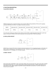
...acording to protect over voltage and noise, When more than 385V is applied, the thermaFfuse(130°C cut-off, local option) in a first part of TRANS is cut so that SPECIFICATION is changed, the calculated time in IC1 is 5V during the general operation. -21 - At the early... oT CIRCUIT for occurring CLOCK which motivates the internal local element of MICOM for supplying electricity to operate. 3) RESET CIRCUIT _ESET All the internal parts of electric power circuits for RELAY driving electricity (12Vdc) and for the fixed time. The RESET terminal is changed or IC1 isn't able to...
...acording to protect over voltage and noise, When more than 385V is applied, the thermaFfuse(130°C cut-off, local option) in a first part of TRANS is cut so that SPECIFICATION is changed, the calculated time in IC1 is 5V during the general operation. -21 - At the early... oT CIRCUIT for occurring CLOCK which motivates the internal local element of MICOM for supplying electricity to operate. 3) RESET CIRCUIT _ESET All the internal parts of electric power circuits for RELAY driving electricity (12Vdc) and for the fixed time. The RESET terminal is changed or IC1 isn't able to...
User Guide
Page 20
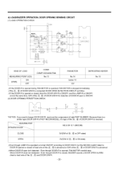
... is abnormal. fcVVhen DOOR-R open is ONIOFR (2) DOOR OPENING PERCEPTION CHECK CON3 _E *NOTICE: If you would change DOOR S/W-R, must use the componenot of right PART NUMBER, Because there is a similar type DOOR StW-R of NOT MICOM MODEL, it's logic of the (_, (_ of DOOR StW-R is reversed. _MEASURING REFRIGERATDO_R POINT NO...
... is abnormal. fcVVhen DOOR-R open is ONIOFR (2) DOOR OPENING PERCEPTION CHECK CON3 _E *NOTICE: If you would change DOOR S/W-R, must use the componenot of right PART NUMBER, Because there is a similar type DOOR StW-R of NOT MICOM MODEL, it's logic of the (_, (_ of DOOR StW-R is reversed. _MEASURING REFRIGERATDO_R POINT NO...
User Guide
Page 25
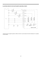
8) LIGHTING CIRCUITS OF KEY BUTTON INPUT AND DISPLAY PARTS 28 27 R04 R05 25 R06 R07 24 22 R4_ KR%O6M Q2 CON5 9 CON101 SCAN2 8 SCAN1 KRAIO6M Ew_ Q3 KRAIO6M 180 R12 180 7 SCANO L1 L2 6 DSPO _ L5_ 5 }SP1 VAC 4 }SP2 ./ _CC6 _7 lo2 IR14 5 /o SV,lg2 ya sva0,_ VACATION FREEZER TEMP QUICK FREEZE KEY CONTROL KEY KEY DISPLAY PART j The above circuit is operated by SCAN method. - 27 - It is to judge the operation conditions of function key and to light each function indicating LED.
8) LIGHTING CIRCUITS OF KEY BUTTON INPUT AND DISPLAY PARTS 28 27 R04 R05 25 R06 R07 24 22 R4_ KR%O6M Q2 CON5 9 CON101 SCAN2 8 SCAN1 KRAIO6M Ew_ Q3 KRAIO6M 180 R12 180 7 SCANO L1 L2 6 DSPO _ L5_ 5 }SP1 VAC 4 }SP2 ./ _CC6 _7 lo2 IR14 5 /o SV,lg2 ya sva0,_ VACATION FREEZER TEMP QUICK FREEZE KEY CONTROL KEY KEY DISPLAY PART j The above circuit is operated by SCAN method. - 27 - It is to judge the operation conditions of function key and to light each function indicating LED.

User Guide
Page 29
3) PWB ASS'Y, DISPLAY AND PARTS LIST _ = _ NO, D_, NO, __ DESCRIP_ON 1 6870JB2025 PWB,DISPLAY 2 6630JB8OOSB WAFER __ MA_RIAL _1'_1€ SPED* FR-1(DS-1107A_ 3MAW250-O 6600JB8004_ TACT S/W _r -- 6600JB8OOSh TACT S/W 5
3) PWB ASS'Y, DISPLAY AND PARTS LIST _ = _ NO, D_, NO, __ DESCRIP_ON 1 6870JB2025 PWB,DISPLAY 2 6630JB8OOSB WAFER __ MA_RIAL _1'_1€ SPED* FR-1(DS-1107A_ 3MAW250-O 6600JB8004_ TACT S/W _r -- 6600JB8OOSh TACT S/W 5


