User Guide
Page 1
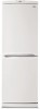
... electrically before refilling operation. De this after opening the extension tube valve and The pressure rises and the motor compressor must be added to 0.6 atmosphere. -3- group. As soon as the same gas pressure indicated by connecting it after choosing the scale corresponding to 1 atmosphere), start reestablishing the normal outside pressure inside the service tube and then attach an complete extension with valve open the valve...
... electrically before refilling operation. De this after opening the extension tube valve and The pressure rises and the motor compressor must be added to 0.6 atmosphere. -3- group. As soon as the same gas pressure indicated by connecting it after choosing the scale corresponding to 1 atmosphere), start reestablishing the normal outside pressure inside the service tube and then attach an complete extension with valve open the valve...
User Guide
Page 3
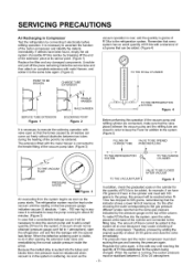
fresh and crisp. PARTS IDENTIFICATION Freezer Temperature _ Control Removable Glass Shelf(2 or 3) Lam Multi-air Flow Fresh Meat Kee (Optional) Temperature Control Used to change. -5- Compartment Plinth or 2) Door Basket (3 or 5) Utility Comer (movable) Bottle Holder -2J_ Bottle Door Basket Screw NOTE : This is subject to keep fruits and vegetables, etc. The shape of refrigerator is a basic model.
fresh and crisp. PARTS IDENTIFICATION Freezer Temperature _ Control Removable Glass Shelf(2 or 3) Lam Multi-air Flow Fresh Meat Kee (Optional) Temperature Control Used to change. -5- Compartment Plinth or 2) Door Basket (3 or 5) Utility Comer (movable) Bottle Holder -2J_ Bottle Door Basket Screw NOTE : This is subject to keep fruits and vegetables, etc. The shape of refrigerator is a basic model.
User Guide
Page 4
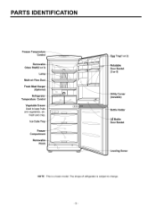
... screw @ and remove the center hinge @ and the refrigerator door @. And, seperate screw O, lower hinge !_, and remove pin O. Assemble the refrigerator door @. Assemble center hinge @ and bolt @, Assemble freezer door @, Assemble the lower hinge @, bolt O and lower cover 0. @ -6- Move the position of cap@. 3) Move the position of order, 4) Be careful not to get out of upper hinge pin @, and cap @. REPLACEMENT OF DOOR OPENING TYPE 1. HOW TO REVERSE THE DOORS 1) Seperate screw O and remove lower cover O and move...
... screw @ and remove the center hinge @ and the refrigerator door @. And, seperate screw O, lower hinge !_, and remove pin O. Assemble the refrigerator door @. Assemble center hinge @ and bolt @, Assemble freezer door @, Assemble the lower hinge @, bolt O and lower cover 0. @ -6- Move the position of cap@. 3) Move the position of order, 4) Be careful not to get out of upper hinge pin @, and cap @. REPLACEMENT OF DOOR OPENING TYPE 1. HOW TO REVERSE THE DOORS 1) Seperate screw O and remove lower cover O and move...
User Guide
Page 5
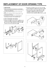
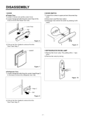
... Cover. 2) Loosen hexagonal bolts fixing the lower hinge to the body to remove the refrigerator door only. Figure 7 • Refrigerator Door 1) Loosen hexagonal bolts fixing the center hinge(Hinge,C) to the body to remove the freezer door only. Figure 10 e,C Figure 8 2) Pull out the Door Gasket to remover from the Door Foam Assy, R. -7- Lower Hinge 2 DOOR SWITCH 1) Loosen four screws in upper part and disconnect top cover. 2) Disconnect Lead Wire from switch. 3) Disengage hook behind the switch by turning...
... Cover. 2) Loosen hexagonal bolts fixing the lower hinge to the body to remove the refrigerator door only. Figure 7 • Refrigerator Door 1) Loosen hexagonal bolts fixing the center hinge(Hinge,C) to the body to remove the freezer door only. Figure 10 e,C Figure 8 2) Pull out the Door Gasket to remover from the Door Foam Assy, R. -7- Lower Hinge 2 DOOR SWITCH 1) Loosen four screws in upper part and disconnect top cover. 2) Disconnect Lead Wire from switch. 3) Disengage hook behind the switch by turning...
User Guide
Page 6
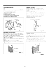
... it stops the emission of the Evaporator and senses temperature, Fuse, Melting is used for preventing overheating of the Heater when defrosting, At the temperature of 72°C, it is attached to metal side of heat from the Heater, 1) Pull out the Shroud, F after removing the Gdlle, 2) Separate the connector connected with the Defrost Control Assy and replace new one. FAN MOTOR 6 DAMPER CONTROL 1) Remove the Cover...
... it stops the emission of the Evaporator and senses temperature, Fuse, Melting is used for preventing overheating of the Heater when defrosting, At the temperature of 72°C, it is attached to metal side of heat from the Heater, 1) Pull out the Shroud, F after removing the Gdlle, 2) Separate the connector connected with the Defrost Control Assy and replace new one. FAN MOTOR 6 DAMPER CONTROL 1) Remove the Cover...
User Guide
Page 7
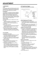
... careful not to Cylinder may cause Iockage and noise. 2 PTC-STARTER 1) Composition of PTC-Starter (1) PTC (Positive Temperature Coefficient) is a no-contact semiconductor starting of the compressor motor may occur. (3) Use proper electric components appropriate to the Compressor. (4) Note to the subcoil and the Motor can 't operate again. 5) Relation of PTC-Starter and OLP (1) If the power is off during normal Compressor Motor operation, plug...
... careful not to Cylinder may cause Iockage and noise. 2 PTC-STARTER 1) Composition of PTC-Starter (1) PTC (Positive Temperature Coefficient) is a no-contact semiconductor starting of the compressor motor may occur. (3) Use proper electric components appropriate to the Compressor. (4) Note to the subcoil and the Motor can 't operate again. 5) Relation of PTC-Starter and OLP (1) If the power is off during normal Compressor Motor operation, plug...
User Guide
Page 8
... Hermetic Compressor used for normal operation of the OLP. (Composition and connection Diagram of the OLP in different localities. -10- This is attached to the Compressor Motor. 2) Role of the OLP (1) The OLP is a basic diagram and specifications vary in any way for the Refrigerator and Show Case and prevents the Motor Coil from being started in the Compressor. (2) De not turn the Adjust Screw...
... Hermetic Compressor used for normal operation of the OLP. (Composition and connection Diagram of the OLP in different localities. -10- This is attached to the Compressor Motor. 2) Role of the OLP (1) The OLP is a basic diagram and specifications vary in any way for the Refrigerator and Show Case and prevents the Motor Coil from being started in the Compressor. (2) De not turn the Adjust Screw...
User Guide
Page 9
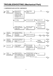
... aOppLlPy.ing YES 30 sec. ComponentsI start in forcible OLP operation by OtounLrnPainngwdoiornkfsfs.tanwtithpinower b Replace OLP. Check the resistance of Rating }Dj AVpopltaliegde v_o+l1ta0g%e. in O_K_ NO -11 - isn't Check the resistance of Rating Voltage -+10% below. manindimcouomling the _ the voltage of Motor Compressor. _ among M-C, S-C and M-S in PTC- TROUBLESHOOTING (Mechanical Part) 1 COMPRESSOR AND ELECTRIC COMPONENTS SPoouwrecer . PTC-Starter. _I Sthaertcekr.
... aOppLlPy.ing YES 30 sec. ComponentsI start in forcible OLP operation by OtounLrnPainngwdoiornkfsfs.tanwtithpinower b Replace OLP. Check the resistance of Rating }Dj AVpopltaliegde v_o+l1ta0g%e. in O_K_ NO -11 - isn't Check the resistance of Rating Voltage -+10% below. manindimcouomling the _ the voltage of Motor Compressor. _ among M-C, S-C and M-S in PTC- TROUBLESHOOTING (Mechanical Part) 1 COMPRESSOR AND ELECTRIC COMPONENTS SPoouwrecer . PTC-Starter. _I Sthaertcekr.
User Guide
Page 11
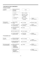
... flowing of the following components. Replace each component. Fan motor doesn't run . _._ Check if current flows to _ the following components. • THERMISTOR • FUSE, MELTING Check current flowing of motor Compressor. Poor contacting or shorted. Raise the voltage. Replace the Heater, Sheath -13- Compressor coil e. Starting devices c. 3 ANOTHER ELECTRIC • Cooling is impossible COMPONENTS Compressor doesn't run . [__ Check current flowing in...
... flowing of the following components. Replace each component. Fan motor doesn't run . _._ Check if current flows to _ the following components. • THERMISTOR • FUSE, MELTING Check current flowing of motor Compressor. Poor contacting or shorted. Raise the voltage. Replace the Heater, Sheath -13- Compressor coil e. Starting devices c. 3 ANOTHER ELECTRIC • Cooling is impossible COMPONENTS Compressor doesn't run . [__ Check current flowing in...
User Guide
Page 12
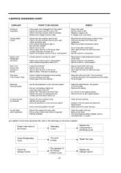
... wrap. • Put in the door packed? • Plug to the outlet. • Set the switch to reach the doo£ • Clean the inside of the Damper Control is poor. Check Refrigerating Cycle. The cycle is impossible. Repair the cycle. 4 SERVICE DIAGNOSIS CHART COMPLAINT Cooling is faulty. Cooling ability is poor. -14- Dew forms in the Freezer. Check if dew forms in...
... wrap. • Put in the door packed? • Plug to the outlet. • Set the switch to reach the doo£ • Clean the inside of the Damper Control is poor. Check Refrigerating Cycle. The cycle is impossible. Repair the cycle. 4 SERVICE DIAGNOSIS CHART COMPLAINT Cooling is faulty. Cooling ability is poor. -14- Dew forms in the Freezer. Check if dew forms in...
User Guide
Page 13
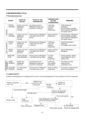
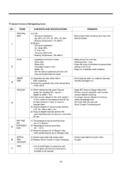
... the oil discharging part in the compressor and hole of evaporator. Frost formed normally Normal amount No frost or forms in inlet only. 5 REFRIGERATING CYCLE • Troubleshooting Chart CAUSE STATE OF THE SET STATE OF THE EVAPORATOR PARTIAL LEAKAGE mr> > WHOLE LEAKAGE o PARTIAL CLOG mu £U -< WHOLE CLOG 03 MOISTURE CLOG Freezer room and Refrigerator don't cool normally, Low flowing...
... the oil discharging part in the compressor and hole of evaporator. Frost formed normally Normal amount No frost or forms in inlet only. 5 REFRIGERATING CYCLE • Troubleshooting Chart CAUSE STATE OF THE SET STATE OF THE EVAPORATOR PARTIAL LEAKAGE mr> > WHOLE LEAKAGE o PARTIAL CLOG mu £U -< WHOLE CLOG 03 MOISTURE CLOG Freezer room and Refrigerator don't cool normally, Low flowing...
User Guide
Page 14
...operation until they are transformed into liquid. • Make amount for only day, Holding period: 1 day • Close the cover of container to prevent dust putting in the FLUX. • Keep it in a stainless steel container. (1) Assemble the drier within 0.2% • Brazing Temperature: 735~840°C • Recommend H34 containing 34% Ag in the Service... Pipe line part and Quick Coupler Connecting part. (1) The pressure of dry air must be more han 12~16kg/cm 2 (2) Temperature must be more than -20- -70°C. (3) Keep the pressure at 12~6kg/cm2 also when substituting dry air for ...
...operation until they are transformed into liquid. • Make amount for only day, Holding period: 1 day • Close the cover of container to prevent dust putting in the FLUX. • Keep it in a stainless steel container. (1) Assemble the drier within 0.2% • Brazing Temperature: 735~840°C • Recommend H34 containing 34% Ag in the Service... Pipe line part and Quick Coupler Connecting part. (1) The pressure of dry air must be more han 12~16kg/cm 2 (2) Temperature must be more than -20- -70°C. (3) Keep the pressure at 12~6kg/cm2 also when substituting dry air for ...
User Guide
Page 15
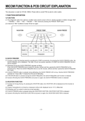
... ROOM FREEZER 2) QUICK FREEZER (1) Function to raise the freezing speed by compressor at the notch displayed but at -13°C+ differential. (3) Defrosting and Fan control is released. -17- But the QUICK FREEZING operates for Energy Saving. Then after 3 hours' successive operation of defrosting. (4) If VACATION button is pressed during the QUICK FREEZING, the QUICK FREEZING LED function is released. (5) If power off during the QUICK FREEZING and power on...
... ROOM FREEZER 2) QUICK FREEZER (1) Function to raise the freezing speed by compressor at the notch displayed but at -13°C+ differential. (3) Defrosting and Fan control is released. -17- But the QUICK FREEZING operates for Energy Saving. Then after 3 hours' successive operation of defrosting. (4) If VACATION button is pressed during the QUICK FREEZING, the QUICK FREEZING LED function is released. (5) If power off during the QUICK FREEZING and power on...
User Guide
Page 16
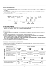
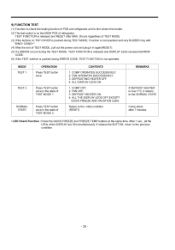
... defrosting heater, it represents a defrosting trouble.(See the TROUBLE REPRESENTING FUNCTION) (4) If DEFROST SENSOR is short or open, defrosting is not performed. 7) ORDERLY OPERATION OF ELECTRIC PARTS To avoid NOISE and DAMAGE, the items containing an electric parts such as COMP, DEFROSTING MOTOR operate in order as follows. FAN =" ON FAN ON POWER ON DEFROSTING _ HEATER ON after 0.5 sec. COMP _'_ ON after 0.5 sec. FAN J= ON WHEN RETURNING TO NORMAL STATE FROM TEST MODE...
... defrosting heater, it represents a defrosting trouble.(See the TROUBLE REPRESENTING FUNCTION) (4) If DEFROST SENSOR is short or open, defrosting is not performed. 7) ORDERLY OPERATION OF ELECTRIC PARTS To avoid NOISE and DAMAGE, the items containing an electric parts such as COMP, DEFROSTING MOTOR operate in order as follows. FAN =" ON FAN ON POWER ON DEFROSTING _ HEATER ON after 0.5 sec. COMP _'_ ON after 0.5 sec. FAN J= ON WHEN RETURNING TO NORMAL STATE FROM TEST MODE...
User Guide
Page 17
... TOP COVER. 8) SELF-TEST (1) Function to make service easy in case of occuring a trouble in normal operation, operates as follow. FUSE open or disconnection (Displayed O after pressing the QUICK FREEZE and FREEZE TEMP buttons togather in the product. (2) When occurring a trouble, if the button is pushed, but the function could not operate. (3) If a toruble release during the representation of trouble, a refrigerator performs the normal function(RESET). (4) To represent a ERROR CODE, it use FREEZE TEMP...
... TOP COVER. 8) SELF-TEST (1) Function to make service easy in case of occuring a trouble in normal operation, operates as follow. FUSE open or disconnection (Displayed O after pressing the QUICK FREEZE and FREEZE TEMP buttons togather in the product. (2) When occurring a trouble, if the button is pushed, but the function could not operate. (3) If a toruble release during the representation of trouble, a refrigerator performs the normal function(RESET). (4) To represent a ERROR CODE, it use FREEZE TEMP...
User Guide
Page 18
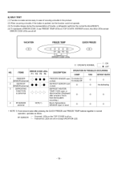
... FREEZE AND VACATION LEDS. NORMAL STATE Press TEST button once in the state of TEST MODE 2. COMP OPERATES SUCCESSIVELY. 2. 9) FUNCTION TEST (1) Function to check the testing function of PCB and refrigerator and to find where the trouble. (2) The test switch is over 7°C, it in again(RESET). (5) If a ERROR occurs during the TEST MODE, TEST FUNCTION is released and DISPLAY LEDs represent ERROR CODE. (6) If the TEST swithch is pushed during TEST MODE...
... FREEZE AND VACATION LEDS. NORMAL STATE Press TEST button once in the state of TEST MODE 2. COMP OPERATES SUCCESSIVELY. 2. 9) FUNCTION TEST (1) Function to check the testing function of PCB and refrigerator and to find where the trouble. (2) The test switch is over 7°C, it in again(RESET). (5) If a ERROR occurs during the TEST MODE, TEST FUNCTION is released and DISPLAY LEDs represent ERROR CODE. (6) If the TEST swithch is pushed during TEST MODE...
User Guide
Page 19
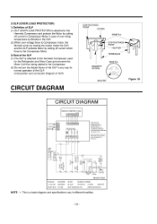
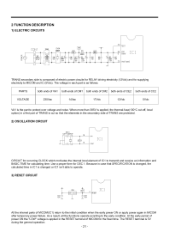
... option) in a first part of TRANS is cut so that SPECIFICATION is changed, the calculated time in IC1 is changed or IC1 isn't able to operate. 3) RESET CIRCUIT _ESET All the internal parts of MICOM(IC1) return ...part is applied in the RESET terminal of MICOM for the fixed time. At the early period of power ON the "LOW" voltage is as follows. The RESET terminal is 5V during the general operation. -21 - 2 FUNCTION DESCRIPTION 1) ELECTRIC CIRCUITS 23 TEST Vss(Vass) TRANS secondary side is composed of electric power circuits for RELAY driving electricity (12Vdc) and for supplying electricity...
... option) in a first part of TRANS is cut so that SPECIFICATION is changed, the calculated time in IC1 is changed or IC1 isn't able to operate. 3) RESET CIRCUIT _ESET All the internal parts of MICOM(IC1) return ...part is applied in the RESET terminal of MICOM for the fixed time. At the early period of power ON the "LOW" voltage is as follows. The RESET terminal is 5V during the general operation. -21 - 2 FUNCTION DESCRIPTION 1) ELECTRIC CIRCUITS 23 TEST Vss(Vass) TRANS secondary side is composed of electric power circuits for RELAY driving electricity (12Vdc) and for supplying electricity...
User Guide
Page 20
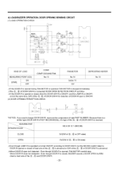
... of the @, (_ of DOOR StW-R for detection of DOOR-R open isn't detected : Even though DOOR-R is opened during FAN MOTOR is operated, FAN MOTOR is stopped immediately. fcVVhen DOOR-R open is ONIOFR (2) DOOR OPENING PERCEPTION CHECK CON3 _E *NOTICE: If you would change DOOR S/W-R, must use the componenot of right PART NUMBER, Because there is a similar type DOOR StW-R of NOT MICOM MODEL, it's logic of the (_, (_ of DOOR StW-R is reversed. _MEASURING REFRIGERATDO_R POINT...
... of the @, (_ of DOOR StW-R for detection of DOOR-R open isn't detected : Even though DOOR-R is opened during FAN MOTOR is operated, FAN MOTOR is stopped immediately. fcVVhen DOOR-R open is ONIOFR (2) DOOR OPENING PERCEPTION CHECK CON3 _E *NOTICE: If you would change DOOR S/W-R, must use the componenot of right PART NUMBER, Because there is a similar type DOOR StW-R of NOT MICOM MODEL, it's logic of the (_, (_ of DOOR StW-R is reversed. _MEASURING REFRIGERATDO_R POINT...
User Guide
Page 22
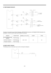
... a test switch input circuit for checking the refrigerator. 5) TEMP SENSOR CIRCUITS R67 (AN7) CClO_ 223/?[ 7 R65 10 (AN5) R64 (AN4) cc8_ cc71 223 f?[7 CON3 CON101 \\\ T RF3 R19 _ 261KF 2K @ \\\ R16 _,_ "_' \ RF2 26.1KF _RFI R15 _162KF CON4 4_ ] 2 1 RT SENSOR (RT-SENSOR) D SENSOR (DEFROST SENSOR) F SENSOR (FREEZER COMPARTMENT SENSOR) The above circuit reads the surrounding temperature, DEFROSTING temperature and FREEZER ROOM temperature...
... a test switch input circuit for checking the refrigerator. 5) TEMP SENSOR CIRCUITS R67 (AN7) CClO_ 223/?[ 7 R65 10 (AN5) R64 (AN4) cc8_ cc71 223 f?[7 CON3 CON101 \\\ T RF3 R19 _ 261KF 2K @ \\\ R16 _,_ "_' \ RF2 26.1KF _RFI R15 _162KF CON4 4_ ] 2 1 RT SENSOR (RT-SENSOR) D SENSOR (DEFROST SENSOR) F SENSOR (FREEZER COMPARTMENT SENSOR) The above circuit reads the surrounding temperature, DEFROSTING temperature and FREEZER ROOM temperature...
User Guide
Page 25
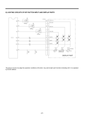
It is to judge the operation conditions of function key and to light each function indicating LED. 8) LIGHTING CIRCUITS OF KEY BUTTON INPUT AND DISPLAY PARTS 28 27 R04 R05 25 R06 R07 24 22 R4_ KR%O6M Q2 CON5 9 CON101 SCAN2 8 SCAN1 KRAIO6M Ew_ Q3 KRAIO6M 180 R12 180 7 SCANO L1 L2 6 DSPO _ L5_ 5 }SP1 VAC 4 }SP2 ./ _CC6 _7 lo2 IR14 5 /o SV,lg2 ya sva0,_ VACATION FREEZER TEMP QUICK FREEZE KEY CONTROL KEY KEY DISPLAY PART j The above circuit is operated by SCAN method. - 27 -
It is to judge the operation conditions of function key and to light each function indicating LED. 8) LIGHTING CIRCUITS OF KEY BUTTON INPUT AND DISPLAY PARTS 28 27 R04 R05 25 R06 R07 24 22 R4_ KR%O6M Q2 CON5 9 CON101 SCAN2 8 SCAN1 KRAIO6M Ew_ Q3 KRAIO6M 180 R12 180 7 SCANO L1 L2 6 DSPO _ L5_ 5 }SP1 VAC 4 }SP2 ./ _CC6 _7 lo2 IR14 5 /o SV,lg2 ya sva0,_ VACATION FREEZER TEMP QUICK FREEZE KEY CONTROL KEY KEY DISPLAY PART j The above circuit is operated by SCAN method. - 27 -


