User Guide
Page 2
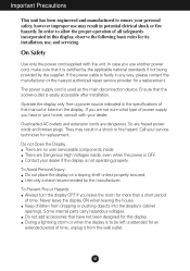
... ensure your personal safety, however improper use may result in potential eletrical shock or fire hazards. In case you have not been designed for this manual or listed on a sloping shelf unless properly secured. Do not Open the Display. To Prevent Fire or Hazards: Always turn the display OFF if you...
... ensure your personal safety, however improper use may result in potential eletrical shock or fire hazards. In case you have not been designed for this manual or listed on a sloping shelf unless properly secured. Do not Open the Display. To Prevent Fire or Hazards: Always turn the display OFF if you...
User Guide
Page 6
... adjusts the display to model. 1 Wall-outlet type 2 PC-outlet type PC MAC 3. button on the front switch panel to manually run this option initializes all the menu items except 'Language'. This function provides the user with optimal display settings.When the user connects the... monitor for individual input signals. This rear view represents a general model; Otherwise, you want to a 15 pin 2 row connector. A5 However, ...
... adjusts the display to model. 1 Wall-outlet type 2 PC-outlet type PC MAC 3. button on the front switch panel to manually run this option initializes all the menu items except 'Language'. This function provides the user with optimal display settings.When the user connects the... monitor for individual input signals. This rear view represents a general model; Otherwise, you want to a 15 pin 2 row connector. A5 However, ...
User Guide
Page 11
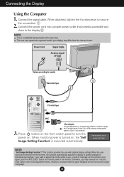
Press the MENU Button, then the main menu of selecting and adjusting an item using the OSD system. On Screen Display(OSD) Selection and Adjustment You were introduced to the procedure of the OSD appears. Menu Name PICTURE Icons Sub-menus Button Tip MENU : Exit - + : Adjust (Decrease/Increase) SET : Enter : Select another sub-menu NOTE OSD (On Screen Display) menu languages on the Menu. A10 Listed below are the icons, icon names, and icon descriptions of the all items shown on the monitor may differ from the manual.
Press the MENU Button, then the main menu of selecting and adjusting an item using the OSD system. On Screen Display(OSD) Selection and Adjustment You were introduced to the procedure of the OSD appears. Menu Name PICTURE Icons Sub-menus Button Tip MENU : Exit - + : Adjust (Decrease/Increase) SET : Enter : Select another sub-menu NOTE OSD (On Screen Display) menu languages on the Menu. A10 Listed below are the icons, icon names, and icon descriptions of the all items shown on the monitor may differ from the manual.
User Guide
Page 14
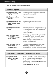
... the 'Specifications' section of the display connected? Do you see a "OSD LOCKED" message on the PC. No image appears Is the power cord of this manual and configure your display is in power saving mode, try again. Is the power on ? You can secure the current control settings, so that they...
... the 'Specifications' section of the display connected? Do you see a "OSD LOCKED" message on the PC. No image appears Is the power cord of this manual and configure your display is in power saving mode, try again. Is the power on ? You can secure the current control settings, so that they...
Service Manual
Page 1
Website:http://biz.LGservice.com E-mail:http://www.LGEservice.com/techsup.html COLOR MONITOR SERVICE MANUAL CHASSIS NO. : CL-82 MODEL: L1717S (L1717S-SNN.AN**EP) L1717S (L1717S-BNN.AN**EP) L1717S (L1717S-GNN.AN**EP) ( ) **Same model for Service CAUTION BEFORE SERVICING THE UNIT, READ THE SAFETY PRECAUTIONS IN THIS MANUAL. - + *To apply the MSTAR Chip.
Website:http://biz.LGservice.com E-mail:http://www.LGEservice.com/techsup.html COLOR MONITOR SERVICE MANUAL CHASSIS NO. : CL-82 MODEL: L1717S (L1717S-SNN.AN**EP) L1717S (L1717S-BNN.AN**EP) L1717S (L1717S-GNN.AN**EP) ( ) **Same model for Service CAUTION BEFORE SERVICING THE UNIT, READ THE SAFETY PRECAUTIONS IN THIS MANUAL. - + *To apply the MSTAR Chip.
Service Manual
Page 4
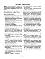
...leads electrically shorted together by conductive foam, aluminum foil or comparable conductive material). 7. Unless specified otherwise in this service manual, lubrication of electrolytic capacitors may result in not required. 6. Alternatively, obtain and wear a commercially available discharging wrist ...remove the test receiver ground lead last. 9. After removing an electrical assembly equipped with an electrolytic capacitor in this service manual, clean electrical contacts only by applying the following mixture to the contacts with a pipe cleaner, cottontipped stick or comparable...
...leads electrically shorted together by conductive foam, aluminum foil or comparable conductive material). 7. Unless specified otherwise in this service manual, lubrication of electrolytic capacitors may result in not required. 6. Alternatively, obtain and wear a commercially available discharging wrist ...remove the test receiver ground lead last. 9. After removing an electrical assembly equipped with an electrolytic capacitor in this service manual, clean electrical contacts only by applying the following mixture to the contacts with a pipe cleaner, cottontipped stick or comparable...
Service Manual
Page 12
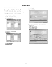
... Manufacture, Serial Number a) Input User Info Data b) Click "Update" button c) Click " Write" button e) Click Start button. Port Setup a) Copy "UserPort.sys" file to LCD Monitor only. 1. ADJUSTMENT Windows EDID V1.0 User Manual Operating System: MS Windows 98, 2000, XP Port Setup: Windows 98 => Don't need setup Windows 2000, XP => Need to Port Setup.
... Manufacture, Serial Number a) Input User Info Data b) Click "Update" button c) Click " Write" button e) Click Start button. Port Setup a) Copy "UserPort.sys" file to LCD Monitor only. 1. ADJUSTMENT Windows EDID V1.0 User Manual Operating System: MS Windows 98, 2000, XP Port Setup: Windows 98 => Don't need setup Windows 2000, XP => Need to Port Setup.
Service Manual
Page 13
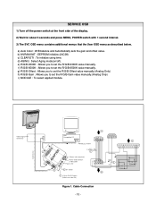
... applied module. g) R/G/B-Offset : Allows you to set the R/G/B-Offset value manually.(Analog Only) h) R/G/B-Gain : Allows you to set the R/G/B-9300K value manually. Video Signal Generator Control Line IBM Compatible PC 15 10 5 PARALLEL PORT Not used RS232C PARALLEL OFF ON 5V C F VGS A MONITOR B V-SYNC ST POWER Power inlet (required) 220 Power Select Switch...
... applied module. g) R/G/B-Offset : Allows you to set the R/G/B-Offset value manually.(Analog Only) h) R/G/B-Gain : Allows you to set the R/G/B-9300K value manually. Video Signal Generator Control Line IBM Compatible PC 15 10 5 PARALLEL PORT Not used RS232C PARALLEL OFF ON 5V C F VGS A MONITOR B V-SYNC ST POWER Power inlet (required) 220 Power Select Switch...
Service Manual
Page 21
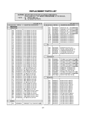
... W 5% 1608 R/TP 4.7K OHM 1/10 W 5% 1608 R/TP - 21 - REPLACEMENT PARTS LIST CAUTION: BEFORE REPLACING ANY OF THESE COMPONENTS, READ CAREFULLY THE SAFETY PRECAUTIONS IN THIS MANUAL. * NOTE : S SAFETY Mark AL ALTERNATIVE PARTS *S *AL LOC. PART NO. DESCRIPTION / SPECIFICATION C204 C205 C206 C207 C211 C213 C214 C215 C216 C217 C218 C219 C220...
... W 5% 1608 R/TP 4.7K OHM 1/10 W 5% 1608 R/TP - 21 - REPLACEMENT PARTS LIST CAUTION: BEFORE REPLACING ANY OF THESE COMPONENTS, READ CAREFULLY THE SAFETY PRECAUTIONS IN THIS MANUAL. * NOTE : S SAFETY Mark AL ALTERNATIVE PARTS *S *AL LOC. PART NO. DESCRIPTION / SPECIFICATION C204 C205 C206 C207 C211 C213 C214 C215 C216 C217 C218 C219 C220...


