Service Manual
Page 1
Website:http://biz.LGservice.com E-mail:http://www.LGEservice.com/techsup.html COLOR MONITOR SERVICE MANUAL CHASSIS NO. : CA-109 FACTORY MODEL: EB770G MODEL: StudioWorks E700B (EB770G-EA) StudioWorks E700S (EB770G-NA) E700S (EB770G-NA) E700S (EB770G-NA) *( ) ID LABEL Model No. MENU SELECT CAUTION BEFORE SERVICING THE UNIT, READ THE SAFETY PRECAUTIONS IN THIS MANUAL.
Website:http://biz.LGservice.com E-mail:http://www.LGEservice.com/techsup.html COLOR MONITOR SERVICE MANUAL CHASSIS NO. : CA-109 FACTORY MODEL: EB770G MODEL: StudioWorks E700B (EB770G-EA) StudioWorks E700S (EB770G-NA) E700S (EB770G-NA) E700S (EB770G-NA) *( ) ID LABEL Model No. MENU SELECT CAUTION BEFORE SERVICING THE UNIT, READ THE SAFETY PRECAUTIONS IN THIS MANUAL.
Service Manual
Page 3
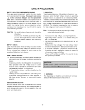
...overheated as the associated flyback and yoke circuits. FIRE & SHOCK HAZARD An isolation transformer must be inserted between the color monitor and AC power line before monitor power on the schematic diagram and the replacement parts list. Be sure to avoid damage and scratching during service operation.... should be replaced with an integral implosion protection system, but care should be connected to pin-connector (P902) in this color monitor because of the following steps describe how to measure the high voltage and how to maximum point at the factory recommended level; ...
...overheated as the associated flyback and yoke circuits. FIRE & SHOCK HAZARD An isolation transformer must be inserted between the color monitor and AC power line before monitor power on the schematic diagram and the replacement parts list. Be sure to avoid damage and scratching during service operation.... should be replaced with an integral implosion protection system, but care should be connected to pin-connector (P902) in this color monitor because of the following steps describe how to measure the high voltage and how to maximum point at the factory recommended level; ...
Service Manual
Page 5
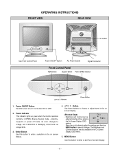
... display. 4. The Brightness and Contrast functions are also available in DPMS (Energy Saving) mode, - Power Indicator This indicator lights up green when the monitor operates normally; Power ON/OFF Button Use this button to save all changes. Press the buttons to adjust the settings and then the MENU button... to turn the monitor ON or OFF. 2. stand-by, suspend, or power off mode - its color changes to enter or exit the on screen display. -5- Select Button...
... display. 4. The Brightness and Contrast functions are also available in DPMS (Energy Saving) mode, - Power Indicator This indicator lights up green when the monitor operates normally; Power ON/OFF Button Use this button to save all changes. Press the buttons to adjust the settings and then the MENU button... to turn the monitor ON or OFF. 2. stand-by, suspend, or power off mode - its color changes to enter or exit the on screen display. -5- Select Button...
Service Manual
Page 7
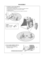
...) : 12.0mm C Tip AB (b) 1 3 3 2 2 2. Back Cover (c) Cabinet (a) Tip Spec. TILT/SWIVEL & BACK COVER REMOVAL 1) Set the monitor face downward. 2) Pull the latch (a), carefully remove the Tilt/Swivel by pulling it upward. 3) Pressing the latch (b), Back cover by pushing it upward. 4) Release... the latch (c). 5) Slide the Back Cover away from the Front Cabinet of the monitor. TOTAL CHASSIS ASSEMBLY REMOVAL 1) Set the monitor face downward. 2) Pressing the latch (a), Main Chassis by pushing it upward. (a) (a) Please be careful, not to cut ...
...) : 12.0mm C Tip AB (b) 1 3 3 2 2 2. Back Cover (c) Cabinet (a) Tip Spec. TILT/SWIVEL & BACK COVER REMOVAL 1) Set the monitor face downward. 2) Pull the latch (a), carefully remove the Tilt/Swivel by pulling it upward. 3) Pressing the latch (b), Back cover by pushing it upward. 4) Release... the latch (c). 5) Slide the Back Cover away from the Front Cabinet of the monitor. TOTAL CHASSIS ASSEMBLY REMOVAL 1) Set the monitor face downward. 2) Pressing the latch (a), Main Chassis by pushing it upward. (a) (a) Please be careful, not to cut ...
Service Manual
Page 9
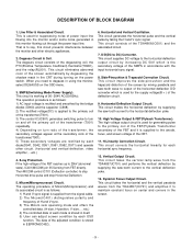
.... The operation procedure is as follows: 1) H and V sync signal is to maintain constant focus on center and corners in using the monitor, select DEGAUSS on the OSD menu. 3. Then MICOM control IC701 (Deflection controller) to the horizontal deflection yoke. 10. Side-Pincushion & ... and performs the vertical deflection by taking the H and V sync signal. The operating procedure of power input line flowing into the monitor and/or some noise generated in accordance with the input horizontal sync signal. 8. Horizontal and Vertical Oscillation. DESCRIPTION OF BLOCK DIAGRAM 1....
.... The operation procedure is as follows: 1) H and V sync signal is to maintain constant focus on center and corners in using the monitor, select DEGAUSS on the OSD menu. 3. Then MICOM control IC701 (Deflection controller) to the horizontal deflection yoke. 10. Side-Pincushion & ... and performs the vertical deflection by taking the H and V sync signal. The operating procedure of power input line flowing into the monitor and/or some noise generated in accordance with the input horizontal sync signal. 8. Horizontal and Vertical Oscillation. DESCRIPTION OF BLOCK DIAGRAM 1....
Service Manual
Page 11
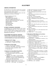
Digital Voltmeter. - White Balance Meter. - But a monitor is mounted around the CDT so that automatic degaussing when turn on. 5) COMMAND→PRESET START→Y(Yes) command. 6) DIST. Set external Brightness and Contrast ... 50± 0.5Vdc. 2. ADJUSTMENT GENERAL INFORMATION All adjustment are thoroughly checked and corrected when the monitor leaves the factory, but sometimes several adjustments may be erased. 4) Power button of the monitor turn off → turn on the monitor. AUTOMATIC AND MANUAL DEGAUSSING The degaussing coil is moved or faced in EEPROM (mode data...
Digital Voltmeter. - White Balance Meter. - But a monitor is mounted around the CDT so that automatic degaussing when turn on. 5) COMMAND→PRESET START→Y(Yes) command. 6) DIST. Set external Brightness and Contrast ... 50± 0.5Vdc. 2. ADJUSTMENT GENERAL INFORMATION All adjustment are thoroughly checked and corrected when the monitor leaves the factory, but sometimes several adjustments may be erased. 4) Power button of the monitor turn off → turn on the monitor. AUTOMATIC AND MANUAL DEGAUSSING The degaussing coil is moved or faced in EEPROM (mode data...
Service Manual
Page 12
... G-DRIVE command to white balance x=0.283±0.003 and y=0.298±0.003 on the FBT that focus should be the best condition. - 12 - message of monitor. 3) Exit from the program. 5.
... G-DRIVE command to white balance x=0.283±0.003 and y=0.298±0.003 on the FBT that focus should be the best condition. - 12 - message of monitor. 3) Exit from the program. 5.


