
Service Manual
Page 1
MODEL : DLE8377WM/DLG8388WM DLE8377NM/DLG8388NM DLE7177WM/DLG7188WM U.S.A. Website: http://us.lgservice.com Canadian Website: http://lg.ca ELECTRIC & GAS DRYER SERVICE MANUAL CAUTION READ THIS MANUAL CAREFULLY IN ORDER TO PROPERLY DIAGNOSE PROBLEMS AND TO SAFELY PROVIDE QUALITY SERVICE ON THESE DRYERS.
MODEL : DLE8377WM/DLG8388WM DLE8377NM/DLG8388NM DLE7177WM/DLG7188WM U.S.A. Website: http://us.lgservice.com Canadian Website: http://lg.ca ELECTRIC & GAS DRYER SERVICE MANUAL CAUTION READ THIS MANUAL CAREFULLY IN ORDER TO PROPERLY DIAGNOSE PROBLEMS AND TO SAFELY PROVIDE QUALITY SERVICE ON THESE DRYERS.

Service Manual
Page 4
INSTALLATION INSTRUCTIONS 6 4. DRYER CYCLE PROCESS ...13 5. GAS MODEL 28 9-8 TEST 8 SEMI-CONDUCTOR 29 10. CONTROL PANEL & PLATE ASSEMBLY 39 12-2. DRUM & MOTOR ASSEMBLY: ELECTRIC MODEL 41 12-3-2. FEATURES ...
INSTALLATION INSTRUCTIONS 6 4. DRYER CYCLE PROCESS ...13 5. GAS MODEL 28 9-8 TEST 8 SEMI-CONDUCTOR 29 10. CONTROL PANEL & PLATE ASSEMBLY 39 12-2. DRUM & MOTOR ASSEMBLY: ELECTRIC MODEL 41 12-3-2. FEATURES ...
Service Manual
Page 5
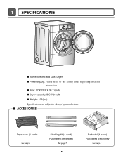
I Dryer capacity: IEC 7.3 cu.ft. I Weight: 126(Ibs) Specifications are subject to the rating label regarding detailed information. I Size: 27 X 29.9 X 38.7 (inch) I ACCESSORIES Dryer rack (1 each) See page 6 Stacking kit (1 each) Purchased Separately See page 7 4 Pedestal (1 each) Purchased Separately See page 8 1 SPECIFICATIONS I Name: Electric and Gas Dryer I Power supply: Please refer to change by manufacturer.
I Dryer capacity: IEC 7.3 cu.ft. I Weight: 126(Ibs) Specifications are subject to the rating label regarding detailed information. I Size: 27 X 29.9 X 38.7 (inch) I ACCESSORIES Dryer rack (1 each) See page 6 Stacking kit (1 each) Purchased Separately See page 7 4 Pedestal (1 each) Purchased Separately See page 8 1 SPECIFICATIONS I Name: Electric and Gas Dryer I Power supply: Please refer to change by manufacturer.
Service Manual
Page 6
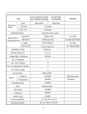
of Programs No. of Dry Options No. of Dry Levels Sound levels Sensor Moisture Temperature Reversible Door Drum Dryer Rack Child Lock Interior Light Product (WxHxD) Packing (WxHxD) Blue White Navy Blue Porcelain Chromate 120V/240V 60Hz (26A)... AC 120V AC 240V (ELECTRIC MODEL) AC 120V AC 120V (GAS MODEL) Electrode sensor Thermistor 5 Net/Gross No. ITEM DLE7177WM/DLE8377WM DLE8377NM DLG7188WM/DLG8388WM DLG8388NM Material & Finish Color Top Plate Door Trim POWER SUPPLY ELECTRICITY CONSUMPTION MOTOR HEATER LAMP GAS VALVE CONTROL TYPE DRUM CAPACITY Weight (lbs)...
of Programs No. of Dry Options No. of Dry Levels Sound levels Sensor Moisture Temperature Reversible Door Drum Dryer Rack Child Lock Interior Light Product (WxHxD) Packing (WxHxD) Blue White Navy Blue Porcelain Chromate 120V/240V 60Hz (26A)... AC 120V AC 240V (ELECTRIC MODEL) AC 120V AC 120V (GAS MODEL) Electrode sensor Thermistor 5 Net/Gross No. ITEM DLE7177WM/DLE8377WM DLE8377NM DLG7188WM/DLG8388WM DLG8388NM Material & Finish Color Top Plate Door Trim POWER SUPPLY ELECTRICITY CONSUMPTION MOTOR HEATER LAMP GAS VALVE CONTROL TYPE DRUM CAPACITY Weight (lbs)...
Service Manual
Page 7
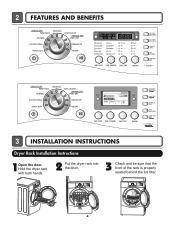
TIME REMAINING OFF MID HIGH 3 INSTALLATION INSTRUCTIONS Dryer Rack Installation Instructions 1Open the door. Hold the dryer rack with both hands. 2 Put the dryer rack into the drum 3 Check and be sure that the front of the rack is properly seated behind the lint filter. 6 2 FEATURES AND BENEFITS 20% NORMAL NORMAL MEDIUM SENSOR DRY 0:20 EST.
TIME REMAINING OFF MID HIGH 3 INSTALLATION INSTRUCTIONS Dryer Rack Installation Instructions 1Open the door. Hold the dryer rack with both hands. 2 Put the dryer rack into the drum 3 Check and be sure that the front of the rack is properly seated behind the lint filter. 6 2 FEATURES AND BENEFITS 20% NORMAL NORMAL MEDIUM SENSOR DRY 0:20 EST.
Service Manual
Page 8
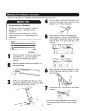
... the side bracket. 6 Insert the front rail of the front rail to the washer with a gas dryer in potentially unstable conditions like a mobile home. 7 Slide the dryer back against the stops on the side brackets. 3 Fit the side bracket firmly to the side of the top plate by placing the legs as... product installation instructions describe in serious physical injury and damage to the appliance. 5 Place the dryer on top of the washer by attaching the double-faced tape to pinch fingers between the washer and...
... the side bracket. 6 Insert the front rail of the front rail to the washer with a gas dryer in potentially unstable conditions like a mobile home. 7 Slide the dryer back against the stops on the side brackets. 3 Fit the side bracket firmly to the side of the top plate by placing the legs as... product installation instructions describe in serious physical injury and damage to the appliance. 5 Place the dryer on top of the washer by attaching the double-faced tape to pinch fingers between the washer and...
Service Manual
Page 9
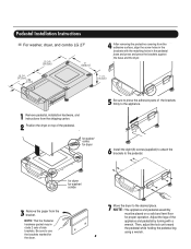
... for proper operation. NOTE : The appliance and pedestal assembly must be placed on top of the pedestal. , for washer/ combo for dryer . Pedestal Installation Instructions For washer, dryer, and combo LG 27" 4 AAtftaecr hretmheovdinogubthle-pfarocteedcttivaepecoovfetrhinegbfroamcktehteto the dardyheersaivsesshuorfwacnes, oaltighne tbhenstcpreawrtshoolfetshien bthreackets ablriagcnkwetisthwtihthetheedgmeaatcnhdincgahnoblees aintttahcehpeeddteostahle pbeadseesatnadl wpritehssscarnedwpsr.ess the brackets against NthOe bTaEse:aAntdtatchhe tdhreyelro.wer...
... for proper operation. NOTE : The appliance and pedestal assembly must be placed on top of the pedestal. , for washer/ combo for dryer . Pedestal Installation Instructions For washer, dryer, and combo LG 27" 4 AAtftaecr hretmheovdinogubthle-pfarocteedcttivaepecoovfetrhinegbfroamcktehteto the dardyheersaivsesshuorfwacnes, oaltighne tbhenstcpreawrtshoolfetshien bthreackets ablriagcnkwetisthwtihthetheedgmeaatcnhdincgahnoblees aintttahcehpeeddteostahle pbeadseesatnadl wpritehssscarnedwpsr.ess the brackets against NthOe bTaEse:aAntdtatchhe tdhreyelro.wer...
Service Manual
Page 10
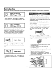
..., use option 3. 5" (12.7 cm) 31/2" (8.6 cm) 1" (2.5 cm) (12.75c" m) 1" (2.5 cm) 4-wire direct 3V2" (8.9 cm) 4-wire connection : Direct wire Important : Grounding through the neutral conductor. Electric Dryer Only Review the following options to determine the appropriate electrical connection for (1) new branch-circuit installations, (2) mobile homes, and (3) recreational vehicles, and (4) areas where local... block(hooked end facing rightward) and pinch the hook together and screw tightly. and be sure that the strain relief screw is in order for dryer to be replaced.
..., use option 3. 5" (12.7 cm) 31/2" (8.6 cm) 1" (2.5 cm) (12.75c" m) 1" (2.5 cm) 4-wire direct 3V2" (8.9 cm) 4-wire connection : Direct wire Important : Grounding through the neutral conductor. Electric Dryer Only Review the following options to determine the appropriate electrical connection for (1) new branch-circuit installations, (2) mobile homes, and (3) recreational vehicles, and (4) areas where local... block(hooked end facing rightward) and pinch the hook together and screw tightly. and be sure that the strain relief screw is in order for dryer to be replaced.
Service Manual
Page 11
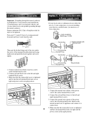
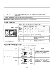
Make sure that the strain relief screw is prohibited for cm) dryer to be sure that all terminal block nuts are installing your local codes or ordinances do not allow the use a 4wire connection. 1. D 2. Remove the neutral ... and a right terminal block screws. Connect red and black wire to the external ground screw. E 3. Option 1: 4-wire connection with a Power supply cord. • lf your dryer in a mobile home, you are on tight and power cord is in right position. D E F a C b C 1. Connect the ground wire (green) of power cord to the left...
Make sure that the strain relief screw is prohibited for cm) dryer to be sure that all terminal block nuts are installing your local codes or ordinances do not allow the use a 4wire connection. 1. D 2. Remove the neutral ... and a right terminal block screws. Connect red and black wire to the external ground screw. E 3. Option 1: 4-wire connection with a Power supply cord. • lf your dryer in a mobile home, you are on tight and power cord is in right position. D E F a C b C 1. Connect the ground wire (green) of power cord to the left...

Service Manual
Page 13
...connections securely. Pipe Plug (for use with the type of gas in your laundry room. Dryer is equipped for checking inlet gas pressure) 3 Equipment Shut-Off Valve-Installed within 6' (1.8 m) of the dryer. Connect to section on Gas Requirements. 1 2 5 3 4 1 New Stainless Steel ...Flexible Connector - For L.P. (Liquefied Petroleum) gas connection, refer to section on Gas Requirements. 1. Make certain your dryer is equipped at the rear of dryer 4 Black Iron Pipe Shorter than 20' (6.1 m) - Make sure you do not damage the pipe thread when removing the cap. ...
...connections securely. Pipe Plug (for use with the type of gas in your laundry room. Dryer is equipped for checking inlet gas pressure) 3 Equipment Shut-Off Valve-Installed within 6' (1.8 m) of the dryer. Connect to section on Gas Requirements. 1 2 5 3 4 1 New Stainless Steel ...Flexible Connector - For L.P. (Liquefied Petroleum) gas connection, refer to section on Gas Requirements. 1. Make certain your dryer is equipped at the rear of dryer 4 Black Iron Pipe Shorter than 20' (6.1 m) - Make sure you do not damage the pipe thread when removing the cap. ...
Service Manual
Page 14
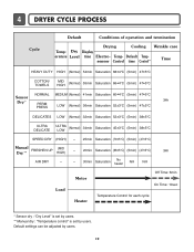
... Time: 10sec Temperature Control for each cycle * Sensor dry : "Dry Level" is set by users. ** Manual dry : "Temperature control" is set by users. 13 Temp- 4 DRYER CYCLE PROCESS Cycle Default Conditions of operation and termination Drying Cooling Wrinkle care Temp- Dry Display erature Level time Electro-
... Time: 10sec Temperature Control for each cycle * Sensor dry : "Dry Level" is set by users. ** Manual dry : "Temperature control" is set by users. 13 Temp- 4 DRYER CYCLE PROCESS Cycle Default Conditions of operation and termination Drying Cooling Wrinkle care Temp- Dry Display erature Level time Electro-
Service Manual
Page 20
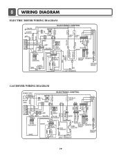
8 WIRING DIAGRAM ELECTRIC DRYER WIRING DIAGRAM PLC MODEM RED WHITE B;ACK ELECTRONIC CONTROL L1 BLACK N WHITE L2 1 WH1 1 2 TRANS BL2 34 3 1 TAP RELAY TAP RELAY BLACK WHITE NA6 6 5 432 1 ... BLUE HEATER 2 1 2 1 MOISTURE THERMISTOR SENSOR RED SAFETY THERMOSTAT OUTER COIL INNER COIL CENTRIFUGAL SWITCH BLOWER WHITE THERMOSTAT RED RED HI - LIMIT THERMOSTAT MOISTURE SENSOR GAS DRYER WIRING DIAGRAM POWER CORD ELECTRONIC CONTROL L1 BLACK N WHITE GN/YL 1 WH1 TRANS 12 BL2 TAP RELAY BLACK YL2 BL3 BLACK WHITE RED NA6 RED...
8 WIRING DIAGRAM ELECTRIC DRYER WIRING DIAGRAM PLC MODEM RED WHITE B;ACK ELECTRONIC CONTROL L1 BLACK N WHITE L2 1 WH1 1 2 TRANS BL2 34 3 1 TAP RELAY TAP RELAY BLACK WHITE NA6 6 5 432 1 ... BLUE HEATER 2 1 2 1 MOISTURE THERMISTOR SENSOR RED SAFETY THERMOSTAT OUTER COIL INNER COIL CENTRIFUGAL SWITCH BLOWER WHITE THERMOSTAT RED RED HI - LIMIT THERMOSTAT MOISTURE SENSOR GAS DRYER WIRING DIAGRAM POWER CORD ELECTRONIC CONTROL L1 BLACK N WHITE GN/YL 1 WH1 TRANS 12 BL2 TAP RELAY BLACK YL2 BL3 BLACK WHITE RED NA6 RED...
Service Manual
Page 22
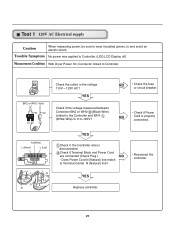
YES Check if the voltage measured between Connector BK2 or WH2- (Black Wire) Linked to Controller. (LED,LCD Display off) Measurement Condition With Dryer Power On; Check if Terminal Block and Power Cord are connected (Check Plug ). BK2 or WH2 WH1 BK WH 12 1 Check the outlet, is properly ...
YES Check if the voltage measured between Connector BK2 or WH2- (Black Wire) Linked to Controller. (LED,LCD Display off) Measurement Condition With Dryer Power On; Check if Terminal Block and Power Cord are connected (Check Plug ). BK2 or WH2 WH1 BK WH 12 1 Check the outlet, is properly ...
Service Manual
Page 23
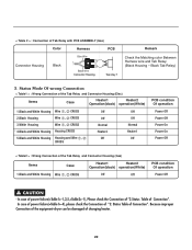
... 1 Tap relay 2 Check the Matching color Between Harness wire and Tab Relay. (White Housing - Turn on Burner Temperature Control below 70 4°C. Measurement Condition With Dryer Power On;
... 1 Tap relay 2 Check the Matching color Between Harness wire and Tab Relay. (White Housing - Turn on Burner Temperature Control below 70 4°C. Measurement Condition With Dryer Power On;
Service Manual
Page 24
... operation Power Off Power Off Power On Power On Power Off < Table2 > : Wrong Connection of changing heater. 23 CAUTION - Because improper Connection of the equipment-dryer can be damaged of the Tab Relay and Connector Housing (Gas) Items Case Heater1 Heater2 Operation(black) operation(White) 1.Black and White Housing Wire , CROSS...
... operation Power Off Power Off Power On Power On Power Off < Table2 > : Wrong Connection of changing heater. 23 CAUTION - Because improper Connection of the equipment-dryer can be damaged of the Tab Relay and Connector Housing (Gas) Items Case Heater1 Heater2 Operation(black) operation(White) 1.Black and White Housing Wire , CROSS...
Service Manual
Page 26
... of Outlet Thermostat attached to blower housing? NO YES Does Idle Switch attached to Motor Bracket operate Level by drum belt? Measurement Condition Turn the Dryer's Power Off, then measure resistance. 1 Idler Switch Lever Idler Switch Is resistance below 3Ω between Connector WH (White wire) and BL2- (Yellow wire)? Test 3 Motor...
... of Outlet Thermostat attached to blower housing? NO YES Does Idle Switch attached to Motor Bracket operate Level by drum belt? Measurement Condition Turn the Dryer's Power Off, then measure resistance. 1 Idler Switch Lever Idler Switch Is resistance below 3Ω between Connector WH (White wire) and BL2- (Yellow wire)? Test 3 Motor...

Service Manual
Page 27
Short with Dry Level. Measurement Condition Turn the Dryer's Power Off, then measure resistance. NO YES Damping cloth When contacting cloth to Controller. Metal or Wire When measuring resistance in the 6 pin connector's Pin (...
Short with Dry Level. Measurement Condition Turn the Dryer's Power Off, then measure resistance. NO YES Damping cloth When contacting cloth to Controller. Metal or Wire When measuring resistance in the 6 pin connector's Pin (...

Service Manual
Page 28
... Door is closed . Check it resistance is open . Check it resistance is not sensed. (Drum motor will flash at 0.5 second intervals.) Measurement Condition After turning Dryer Power Off, measure resistance. YES • Door switch Check (Refer to Component testing.) Measure while Door is open . Check Harness-linking connector. 27 Display will...
... Door is closed . Check it resistance is open . Check it resistance is not sensed. (Drum motor will flash at 0.5 second intervals.) Measurement Condition After turning Dryer Power Off, measure resistance. YES • Door switch Check (Refer to Component testing.) Measure while Door is open . Check Harness-linking connector. 27 Display will...

Service Manual
Page 30
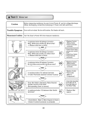
... When measuring Valve 2 voltage, Value is more than1.5 ~ 2.5kΩ? Drying time takes longer. Trouble Symptom While operating, Heating will not work. Measurement Condition With dryer power on Valve 1 and Valve 2, Valves are Off? NO YES • Change Valve • Harness check • Controller change 29 Test 7 GAS Valve test - YES...
... When measuring Valve 2 voltage, Value is more than1.5 ~ 2.5kΩ? Drying time takes longer. Trouble Symptom While operating, Heating will not work. Measurement Condition With dryer power on Valve 1 and Valve 2, Valves are Off? NO YES • Change Valve • Harness check • Controller change 29 Test 7 GAS Valve test - YES...
Service Manual
Page 31
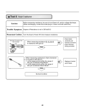
... YES • Check Semiconductor and Harness Connector • Check Harness linking connector When measuring resistance in 300°æ30 Ω Measurement Condition Turn the Dryer's Power Off, then measure resistance.
... YES • Check Semiconductor and Harness Connector • Check Harness linking connector When measuring resistance in 300°æ30 Ω Measurement Condition Turn the Dryer's Power Off, then measure resistance.


