

Service Manual
Page 4
... PROCESS ...13 5. WIRING DIAGRAM ...19 9. TEST 1 120V AC ELECTRICAL SUPPLY 21 9-2. TEST 5 DOOR SWITCH TEST 26 9-6. TEST 7 GAS VALVE TEST - DISASSEMBLY INSTRUCTIONS 32 12. TEST 4 MOISTURE SENSOR 25 9-5. GAS MODEL 28 9-8 TEST 8 SEMI-CONDUCTOR 29 10. EXPLODED VIEW ...39 12-1. CONTROL PANEL & PLATE ASSEMBLY 39 12-2. REPLACEMENT PARTS LIST 43 3 ELECTRIC MODEL...
... PROCESS ...13 5. WIRING DIAGRAM ...19 9. TEST 1 120V AC ELECTRICAL SUPPLY 21 9-2. TEST 5 DOOR SWITCH TEST 26 9-6. TEST 7 GAS VALVE TEST - DISASSEMBLY INSTRUCTIONS 32 12. TEST 4 MOISTURE SENSOR 25 9-5. GAS MODEL 28 9-8 TEST 8 SEMI-CONDUCTOR 29 10. EXPLODED VIEW ...39 12-1. CONTROL PANEL & PLATE ASSEMBLY 39 12-2. REPLACEMENT PARTS LIST 43 3 ELECTRIC MODEL...
Service Manual
Page 6
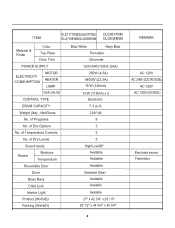
... No. ITEM DLE7177WM/DLE8377WM DLE8377NM DLG7188WM/DLG8388WM DLG8388NM Material & Finish Color Top Plate Door Trim POWER SUPPLY ELECTRICITY CONSUMPTION MOTOR HEATER LAMP GAS VALVE CONTROL TYPE DRUM CAPACITY Weight (lbs) - of Programs No. of Dry Options No. of Temperature Controls No. of Dry Levels Sound levels Sensor Moisture Temperature Reversible Door Drum Dryer... Stainless Steel Available Avaiable Avaiable 27" x 42 3/4" x 28 1/3" 29 1/2" x 44 3/4" x 30 3/4" REMARK AC 120V AC 240V (ELECTRIC MODEL) AC 120V AC 120V (GAS MODEL) Electrode sensor Thermistor 5
... No. ITEM DLE7177WM/DLE8377WM DLE8377NM DLG7188WM/DLG8388WM DLG8388NM Material & Finish Color Top Plate Door Trim POWER SUPPLY ELECTRICITY CONSUMPTION MOTOR HEATER LAMP GAS VALVE CONTROL TYPE DRUM CAPACITY Weight (lbs) - of Programs No. of Dry Options No. of Temperature Controls No. of Dry Levels Sound levels Sensor Moisture Temperature Reversible Door Drum Dryer... Stainless Steel Available Avaiable Avaiable 27" x 42 3/4" x 28 1/3" 29 1/2" x 44 3/4" x 30 3/4" REMARK AC 120V AC 240V (ELECTRIC MODEL) AC 120V AC 120V (GAS MODEL) Electrode sensor Thermistor 5
Service Manual
Page 20
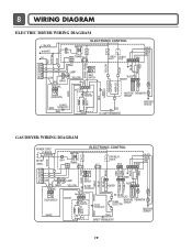
... 1 2 3 7 10 MOTOR WHITE DOOR SWITCH OVERLOAD PROTECTOR BLUE ORANGE RED BLUE HEATER 2 1 2 1 MOISTURE THERMISTOR SENSOR RED SAFETY THERMOSTAT OUTER COIL INNER COIL CENTRIFUGAL SWITCH BLOWER WHITE THERMOSTAT RED RED HI - LIMIT THERMOSTAT MOISTURE SENSOR GAS DRYER WIRING DIAGRAM POWER CORD ELECTRONIC CONTROL L1 BLACK N WHITE GN/YL 1 WH1 TRANS 12...21 21 YELLOW 123 DOOR SWITCH MOTOR 2379 OVERLOAD PROTECTOR HI-LIMIT THERMOSTAT WHITE DC VALVE1 DC VALVE2 MOISTURE THERMISTOR FLAME SENSOR DETECTOR MOISTURE SENSOR CENTRIFUGAL SWITCH RED WHITE NC NO GRAY SAFETY THERMOSTAT 19
... 1 2 3 7 10 MOTOR WHITE DOOR SWITCH OVERLOAD PROTECTOR BLUE ORANGE RED BLUE HEATER 2 1 2 1 MOISTURE THERMISTOR SENSOR RED SAFETY THERMOSTAT OUTER COIL INNER COIL CENTRIFUGAL SWITCH BLOWER WHITE THERMOSTAT RED RED HI - LIMIT THERMOSTAT MOISTURE SENSOR GAS DRYER WIRING DIAGRAM POWER CORD ELECTRONIC CONTROL L1 BLACK N WHITE GN/YL 1 WH1 TRANS 12...21 21 YELLOW 123 DOOR SWITCH MOTOR 2379 OVERLOAD PROTECTOR HI-LIMIT THERMOSTAT WHITE DC VALVE1 DC VALVE2 MOISTURE THERMISTOR FLAME SENSOR DETECTOR MOISTURE SENSOR CENTRIFUGAL SWITCH RED WHITE NC NO GRAY SAFETY THERMOSTAT 19
Service Manual
Page 21
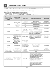
9 DIAGNOSTIC TEST 1. Displays Moisture Sensor Operation: If moisture sensor is open the door Proceed with the step 1 and ...Thermistor close See test 1 Display: See page See test 2 Once Motor Motor runs 70 ~ 239 Measured Moisture Value. Unit must be used for Factory test /Service test. Pressing the START/PAUSE button CHECKING ACTION ...DISPLAY CHECKING POINT REMARK None Electric control & Temperature sensor LQC TEST tE1 tE2 Won't power up Detective LED or LCD Thermistor open the door. Motor & Heater...
9 DIAGNOSTIC TEST 1. Displays Moisture Sensor Operation: If moisture sensor is open the door Proceed with the step 1 and ...Thermistor close See test 1 Display: See page See test 2 Once Motor Motor runs 70 ~ 239 Measured Moisture Value. Unit must be used for Factory test /Service test. Pressing the START/PAUSE button CHECKING ACTION ...DISPLAY CHECKING POINT REMARK None Electric control & Temperature sensor LQC TEST tE1 tE2 Won't power up Detective LED or LCD Thermistor open the door. Motor & Heater...

Service Manual
Page 27
...% ~ 40% 40% ~ 20% Display Value Voltage (DC) (between 6 Pin terminal 50 ~ 130 2.5V 130 ~ 20 2.0V ~ 4.0V ) Remark Weight after removing from the Controller. Test 4 Moisture sensor Caution Before measuring resistance, be sure to Controller. Short with metal to the 6 pin connector's Pin (Blue Wire) and Pin (Orange Wire) to turn Power...
...% ~ 40% 40% ~ 20% Display Value Voltage (DC) (between 6 Pin terminal 50 ~ 130 2.5V 130 ~ 20 2.0V ~ 4.0V ) Remark Weight after removing from the Controller. Test 4 Moisture sensor Caution Before measuring resistance, be sure to Controller. Short with metal to the 6 pin connector's Pin (Blue Wire) and Pin (Orange Wire) to turn Power...
Owners Manual
Page 25
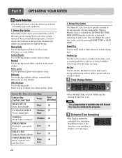
...Heavy Duty Use for drying heavy Fabrics such as work clothes. Speed Dry Use for items that need a short drying time. A sensor detects the moisture in the dryer too long. press Use for permanent press and synthetic items Delicates Use for drying synthetic fabrics, washable knit fabrics ...cycle based on laundry types and conditions. 1. Each cycle dries certain fabrics at the recommended temperature. When a Manual Cycle is set. Sensor Dry Cycles Sensor Dry Cycles allow you to match the cycle to this cycle to select a specific amount of drying time and a drying temperature. Air ...
...Heavy Duty Use for drying heavy Fabrics such as work clothes. Speed Dry Use for items that need a short drying time. A sensor detects the moisture in the dryer too long. press Use for permanent press and synthetic items Delicates Use for drying synthetic fabrics, washable knit fabrics ...cycle based on laundry types and conditions. 1. Each cycle dries certain fabrics at the recommended temperature. When a Manual Cycle is set. Sensor Dry Cycles Sensor Dry Cycles allow you to match the cycle to this cycle to select a specific amount of drying time and a drying temperature. Air ...


