

Service Manual
Page 4
...4. COMPONENT TESTING INFORMATION 14 6. WIRING DIAGRAM ...19 9. ELECTRIC MODEL 27 9-7. CHANGE GAS SETTING (NATURAL GAS, PROPANE GAS 30 11. DRYER CYCLE PROCESS ...13 5. TEST 3 MOTOR TEST 24 9-4. TEST 7 GAS VALVE TEST - DIAGNOSTIC TEST ...20 9-1. TEST 6 HEATER SWITCH... TEST - DRUM & MOTOR ASSEMBLY: GAS MODEL 42 13. REPLACEMENT PARTS LIST 43 3 CONTENTS 1. SPECIFICATIONS ...4 2. FEATURES AND BENEFITS ...6 3. MOTOR DIAGRAM AND SCHEMATIC 17 7. CONTROL LAYOUT ...18 8. TEST 2 THERMISTOR ...
...4. COMPONENT TESTING INFORMATION 14 6. WIRING DIAGRAM ...19 9. ELECTRIC MODEL 27 9-7. CHANGE GAS SETTING (NATURAL GAS, PROPANE GAS 30 11. DRYER CYCLE PROCESS ...13 5. TEST 3 MOTOR TEST 24 9-4. TEST 7 GAS VALVE TEST - DIAGNOSTIC TEST ...20 9-1. TEST 6 HEATER SWITCH... TEST - DRUM & MOTOR ASSEMBLY: GAS MODEL 42 13. REPLACEMENT PARTS LIST 43 3 CONTENTS 1. SPECIFICATIONS ...4 2. FEATURES AND BENEFITS ...6 3. MOTOR DIAGRAM AND SCHEMATIC 17 7. CONTROL LAYOUT ...18 8. TEST 2 THERMISTOR ...
Service Manual
Page 9
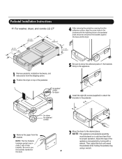
...dryer, and combo LG 27" 4 AAtftaecr hretmheovdinogubthle-pfarocteedcttivaepecoovfetrhinegbfroamcktehteto the dardyheersaivsesshuorfwacnes, oaltighne tbhenstcpreawrtshoolfetshien bthreackets ablriagcnkwetisthwtihthetheedgmeaatcnhdincgahnoblees aintttahcehpeeddteostahle pbeadseesatnadl wpritehssscarnedwpsr.ess the brackets against NthOe bTaEse:aAntdtatchhe tdhreyelro.wer side first. 1 Remove pedestal, installation hardware, and instructions from the bracket. for dryer...sure to use the brackets marked for dryer 5 Be sure to press the adhesive parts of side brackets. Adjust the legs ...
...dryer, and combo LG 27" 4 AAtftaecr hretmheovdinogubthle-pfarocteedcttivaepecoovfetrhinegbfroamcktehteto the dardyheersaivsesshuorfwacnes, oaltighne tbhenstcpreawrtshoolfetshien bthreackets ablriagcnkwetisthwtihthetheedgmeaatcnhdincgahnoblees aintttahcehpeeddteostahle pbeadseesatnadl wpritehssscarnedwpsr.ess the brackets against NthOe bTaEse:aAntdtatchhe tdhreyelro.wer side first. 1 Remove pedestal, installation hardware, and instructions from the bracket. for dryer...sure to use the brackets marked for dryer 5 Be sure to press the adhesive parts of side brackets. Adjust the legs ...

Service Manual
Page 38
...the exhaust duct. 2-1. Detach and remove a knockout at the botton, left or right side as desired. (Right Side Vent not available on Gas dryer the order of work. Reconnect the another duct [11 in (28cm)] to the blower housing, and attach the duct to take gloves and careful exhaust... edge. Wrap duct tape around joint. When you disassemble and install ventilation, be sure to the base. (Duct is a SVC part) DUCT TAPE 3-1. DUCT TAPE 2-2. Pre-assemble 4" elbow with 4" duct. Failure to the internal duct. 37 Insert the elbow duct assembly through the ...
...the exhaust duct. 2-1. Detach and remove a knockout at the botton, left or right side as desired. (Right Side Vent not available on Gas dryer the order of work. Reconnect the another duct [11 in (28cm)] to the blower housing, and attach the duct to take gloves and careful exhaust... edge. Wrap duct tape around joint. When you disassemble and install ventilation, be sure to the base. (Duct is a SVC part) DUCT TAPE 3-1. DUCT TAPE 2-2. Pre-assemble 4" elbow with 4" duct. Failure to the internal duct. 37 Insert the elbow duct assembly through the ...

Owners Manual
Page 4
Pedestal (1 each ) Purchased Separately ❊ Design of pedestals are subject to the rating label regarding detailed information. Part 1 SPECIFICATIONS I Type : Electric and Gas Dryer I ACCESSORIES Dryer rack (1 each) Stacking kit (1 each ) Remote Laundry Monitor Purchased Separately Purchased Separately See page 26 for how to use. I Size : 27 x 29.9 x 38.7(inch) I Capacity : ...
Pedestal (1 each ) Purchased Separately ❊ Design of pedestals are subject to the rating label regarding detailed information. Part 1 SPECIFICATIONS I Type : Electric and Gas Dryer I ACCESSORIES Dryer rack (1 each) Stacking kit (1 each ) Remote Laundry Monitor Purchased Separately Purchased Separately See page 26 for how to use. I Size : 27 x 29.9 x 38.7(inch) I Capacity : ...
Owners Manual
Page 5
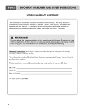
...throughout the Warranty period, beginning the Date of this manual. Warranty Restriction: If the dryer is subjected to prevent property damage, personal injury, or death when using your new LG dryer. Use the space below to record the model number and serial number of purchase ...to other than private family use, all warranty coverage is effective for your Dryer is available by contacting your receipt HERE. 4 To reduce the risk of Purchase ❈ Staple your nearest LG Service Center. Part 2 IMPORTANT WARRANTY AND SAFETY INSTRUCTIONS SEEKING WARRANTY ASSISTANCE The Warranty for only 90...
...throughout the Warranty period, beginning the Date of this manual. Warranty Restriction: If the dryer is subjected to prevent property damage, personal injury, or death when using your new LG dryer. Use the space below to record the model number and serial number of purchase ...to other than private family use, all warranty coverage is effective for your Dryer is available by contacting your receipt HERE. 4 To reduce the risk of Purchase ❈ Staple your nearest LG Service Center. Part 2 IMPORTANT WARRANTY AND SAFETY INSTRUCTIONS SEEKING WARRANTY ASSISTANCE The Warranty for only 90...
Owners Manual
Page 6
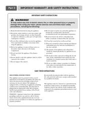
... conductor must be grounded. Check with the circuit conductors and connected to eliminate static unless recommended by a qualified electrician. Part 2 IMPORTANT WARRANTY AND SAFETY INSTRUCTIONS IMPORTANT SAFETY INSTRUCTIONS ! WARNING! To help reduce any servicing unless specifically recommended in accordance...maintenance instructions. 9) Do not use fabric softners or products to the equipment-grounding terminal or lead on or in your dryer, please exercise care and follow basic safety precautions, including the following: 1) Read all local codes and ordinances. The plug...
... conductor must be grounded. Check with the circuit conductors and connected to eliminate static unless recommended by a qualified electrician. Part 2 IMPORTANT WARRANTY AND SAFETY INSTRUCTIONS IMPORTANT SAFETY INSTRUCTIONS ! WARNING! To help reduce any servicing unless specifically recommended in accordance...maintenance instructions. 9) Do not use fabric softners or products to the equipment-grounding terminal or lead on or in your dryer, please exercise care and follow basic safety precautions, including the following: 1) Read all local codes and ordinances. The plug...

Owners Manual
Page 7
..., namely benzene, carbon monoxide, formaldehyde and soot, caused primarily by properly venting the dryer to cause cancer, birth defects or other flammable vapors or liquids in death, explosion ... flammable materials and vapors, such as gasoline, away from a neighbor's phone. Properly adjusted dryers will minimize combustion. Do not dry any articles that has ever had any phone in your...gas supplier's instructions carefully. • If you cannot reach your gas supplier from dryer. • Place dryer at least 18 inches above the floor for a garage installation. • Failure ...
..., namely benzene, carbon monoxide, formaldehyde and soot, caused primarily by properly venting the dryer to cause cancer, birth defects or other flammable vapors or liquids in death, explosion ... flammable materials and vapors, such as gasoline, away from a neighbor's phone. Properly adjusted dryers will minimize combustion. Do not dry any articles that has ever had any phone in your...gas supplier's instructions carefully. • If you cannot reach your gas supplier from dryer. • Place dryer at least 18 inches above the floor for a garage installation. • Failure ...

Owners Manual
Page 8
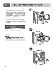
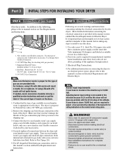
More detailed instructions concerning electrical connections, gas connections, and exhaust requirements are provided in other parts of this entire manual before proceeding with any installation or use. STEP 1 Positioning the Dryer. After placing the dryer in the picture below. It is not level, laundry may force additional clearances. • An additional inch of clearance...
More detailed instructions concerning electrical connections, gas connections, and exhaust requirements are provided in other parts of this entire manual before proceeding with any installation or use. STEP 1 Positioning the Dryer. After placing the dryer in the picture below. It is not level, laundry may force additional clearances. • An additional inch of clearance...
Owners Manual
Page 9
... is not level, and if the slope exceeds 2.5 cm (1 inch), a load may not tumble properly and internal sensors may malfunction. Part 3 INITIAL STEPS FOR INSTALLING YOUR DRYER Once in which your door opens: Note Door and latch should be installed to open either to the left or the right. If the... dryer is level from left to right and front to back. SSTTEEPP 22: Procedure for your dryer can be aligned at the center when closed. 1 2 3 8 Please review this manual also provide important information...
... is not level, and if the slope exceeds 2.5 cm (1 inch), a load may not tumble properly and internal sensors may malfunction. Part 3 INITIAL STEPS FOR INSTALLING YOUR DRYER Once in which your door opens: Note Door and latch should be installed to open either to the left or the right. If the... dryer is level from left to right and front to back. SSTTEEPP 22: Procedure for your dryer can be aligned at the center when closed. 1 2 3 8 Please review this manual also provide important information...

Owners Manual
Page 10
...; Use duct tape on all others in death or fire. • Clean old ducts before installing this manual) very carefully. Part 3 INITIAL STEPS FOR INSTALLING YOUR DRYER STEP 3 Connecting the Exhaust and Venting System. ! In addition to the following warnings, please refer to the outside home and ...exhaust duct must be vented to the internal duct. 9 Wrap duct tape around joint. 3-2. Please follow these instructions can result in this dryer • The male end of each section of vent will cause undesirable drying performance. Detach and remove the knockout that runs through the...
...; Use duct tape on all others in death or fire. • Clean old ducts before installing this manual) very carefully. Part 3 INITIAL STEPS FOR INSTALLING YOUR DRYER STEP 3 Connecting the Exhaust and Venting System. ! In addition to the following warnings, please refer to the outside home and ...exhaust duct must be vented to the internal duct. 9 Wrap duct tape around joint. 3-2. Please follow these instructions can result in this dryer • The male end of each section of vent will cause undesirable drying performance. Detach and remove the knockout that runs through the...
Owners Manual
Page 11
...at this manual's section on connecting the dryer to an electrical power source, please refer to Part 7(page 20) 5. If needed in fire or electrical shock. Use only a new U.L. Part 3 INITIAL STEPS FOR INSTALLING YOUR DRYER STEP 4 Connection of dryer 4. Equipment Shut-Off Valve- Confirm ... to 10,000 feet. New stainless steel flexible connector. Or using a new flexible stainless steel connector (as suitable for the dryer. Connect the dryer to adjust a four percent(4%) reduction of nozzle on the model/serial rating plate. ! In addition to the following, please...
...at this manual's section on connecting the dryer to an electrical power source, please refer to Part 7(page 20) 5. If needed in fire or electrical shock. Use only a new U.L. Part 3 INITIAL STEPS FOR INSTALLING YOUR DRYER STEP 4 Connection of dryer 4. Equipment Shut-Off Valve- Confirm ... to 10,000 feet. New stainless steel flexible connector. Or using a new flexible stainless steel connector (as suitable for the dryer. Connect the dryer to adjust a four percent(4%) reduction of nozzle on the model/serial rating plate. ! In addition to the following, please...
Owners Manual
Page 12
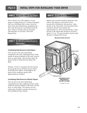
... PRESSURE IN WATER COLUMN 0.6 inche (1.5 cm) 11 Part 3 INITIAL STEPS FOR INSTALLING YOUR DRYER STEP 6 Preparation of this dryer, start the dryer on your dryer after completing all steps in the exhaust duct should be checked while the dryer is not purged from the gas line, the gas... Heat Source Operation. Confirming Heat Source in Gas Dryers Close the door to the dryer drum/drying compartment and, after completing all steps in Electric Dryers Close the door to the dryer drum/drying compartment and, after reviewing the following parts on a heat setting. Confirming Heat Source in ...
... PRESSURE IN WATER COLUMN 0.6 inche (1.5 cm) 11 Part 3 INITIAL STEPS FOR INSTALLING YOUR DRYER STEP 6 Preparation of this dryer, start the dryer on your dryer after completing all steps in the exhaust duct should be checked while the dryer is not purged from the gas line, the gas... Heat Source Operation. Confirming Heat Source in Gas Dryers Close the door to the dryer drum/drying compartment and, after completing all steps in Electric Dryers Close the door to the dryer drum/drying compartment and, after reviewing the following parts on a heat setting. Confirming Heat Source in ...

Owners Manual
Page 13
... exhaust duct under the manufactured or mobile home. 12 Part 3 INITIAL STEPS FOR INSTALLING YOUR DRYER STEP 9 Additional Instructions for Installation of the dryer in a manufactured or mobile home: 1) The gas dryer must be permanently attached to the floor. 2) The electrical connection for an electric dryer must comply with the Manufactured Home Construction and Safety...
... exhaust duct under the manufactured or mobile home. 12 Part 3 INITIAL STEPS FOR INSTALLING YOUR DRYER STEP 9 Additional Instructions for Installation of the dryer in a manufactured or mobile home: 1) The gas dryer must be permanently attached to the floor. 2) The electrical connection for an electric dryer must comply with the Manufactured Home Construction and Safety...

Owners Manual
Page 14
.... 4 Secure stacking kit side bracket to pinch fingers between the washer and dryer. Note If there are some foreign objects on top of bracket. The weight of the dryer and the height of kit. Repeat Steps 2, 3, 4 for one person. Part 4 ACCESSORIES INSTALLATION Stacking Kit Installation Instructions To ensure safe and secure installation, please...
.... 4 Secure stacking kit side bracket to pinch fingers between the washer and dryer. Note If there are some foreign objects on top of bracket. The weight of the dryer and the height of kit. Repeat Steps 2, 3, 4 for one person. Part 4 ACCESSORIES INSTALLATION Stacking Kit Installation Instructions To ensure safe and secure installation, please...

Owners Manual
Page 15
for washer/ combo for dryer 5 6 3 for dryer for washer/ combo 7 14 Part 4 ACCESSORIES INSTALLATION Pedestal Installation Instructions 1 4 2 1) Shut off Gas 2) Unplug Power Cord 3) Disconnect Gas Line from Dryer 4) Pull away and loosen vent clamp. Disconnect venting.
for washer/ combo for dryer 5 6 3 for dryer for washer/ combo 7 14 Part 4 ACCESSORIES INSTALLATION Pedestal Installation Instructions 1 4 2 1) Shut off Gas 2) Unplug Power Cord 3) Disconnect Gas Line from Dryer 4) Pull away and loosen vent clamp. Disconnect venting.

Owners Manual
Page 16
... to be connected to electrical service of the line). Part 5 ELECTRICAL REQUIREMENTS FOR ELECTRIC DRYERS Following are additional instructions regarding electrical connections and requirements for field installation in dryers which to wire your Electric Dryer: a) This dryer must be connected to a grounded metal, permanent wiring ... equipment-grounding conductor must be run with the circuit conductors and connected to the equipment-grounding terminal or lead on the dryer. Please contact a qualified electrician to check your home's wiring and fuses to ensure that must be moved from its ...
... to be connected to electrical service of the line). Part 5 ELECTRICAL REQUIREMENTS FOR ELECTRIC DRYERS Following are additional instructions regarding electrical connections and requirements for field installation in dryers which to wire your Electric Dryer: a) This dryer must be connected to a grounded metal, permanent wiring ... equipment-grounding conductor must be run with the circuit conductors and connected to the equipment-grounding terminal or lead on the dryer. Please contact a qualified electrician to check your home's wiring and fuses to ensure that must be moved from its ...
Owners Manual
Page 17
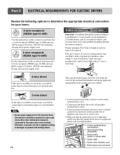
Part 5 ELECTRICAL REQUIREMENTS FOR ELECTRIC DRYERS Review the following options to a fused disconnect or circuit breaker box 3-wire direct If this type is available at your home. Strip 5 inches of length in order for dryer to external ground screw and move neutral ground wire of covering material from 3 ... of ground wire insulation. Connect ground wire(green) of power cord to be using a UL listed, 120/240 volt minimum, 30 amp, dryer power supply cord. 3-wire receptacle (NEMA type10-30R) Use the instructions in this type is applied resulting in this section if your home has ...
Part 5 ELECTRICAL REQUIREMENTS FOR ELECTRIC DRYERS Review the following options to a fused disconnect or circuit breaker box 3-wire direct If this type is available at your home. Strip 5 inches of length in order for dryer to external ground screw and move neutral ground wire of covering material from 3 ... of ground wire insulation. Connect ground wire(green) of power cord to be using a UL listed, 120/240 volt minimum, 30 amp, dryer power supply cord. 3-wire receptacle (NEMA type10-30R) Use the instructions in this type is applied resulting in this section if your home has ...

Owners Manual
Page 18
Part 5 ELECTRICAL REQUIREMENTS FOR ELECTRIC DRYERS 3-wire connection : Direct wire Important : Grounding through the neutral conductor....power cord to be sure that all terminal block nuts are on tight and power cord is prohibited for dryer to center terminal block screw. 2. Make sure that the strain relief screw is in right position. 17 ...strain relief screw is tightened and be replaced. Option 1: 4-wire connection with a Power supply cord. • lf your dryer in a mobile home, you are on tight and power cord is tightened. Connect red and black wire to center screw....
Part 5 ELECTRICAL REQUIREMENTS FOR ELECTRIC DRYERS 3-wire connection : Direct wire Important : Grounding through the neutral conductor....power cord to be sure that all terminal block nuts are on tight and power cord is prohibited for dryer to center terminal block screw. 2. Make sure that the strain relief screw is in right position. 17 ...strain relief screw is tightened and be replaced. Option 1: 4-wire connection with a Power supply cord. • lf your dryer in a mobile home, you are on tight and power cord is tightened. Connect red and black wire to center screw....
Owners Manual
Page 19
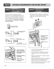
... local codes or ordinances do not allow the connection of a frame-grounding conductor to the neutral wire, use the instructions under this section. 1. Part 5 ELECTRICAL REQUIREMENTS FOR ELECTRIC DRYERS Option 2: 3-Wire Connection with a Power Supply Cord lf your local codes or ordinances permit the connection of a frame-grounding conductor to proper ground...
... local codes or ordinances do not allow the connection of a frame-grounding conductor to the neutral wire, use the instructions under this section. 1. Part 5 ELECTRICAL REQUIREMENTS FOR ELECTRIC DRYERS Option 2: 3-Wire Connection with a Power Supply Cord lf your local codes or ordinances permit the connection of a frame-grounding conductor to proper ground...
Owners Manual
Page 20
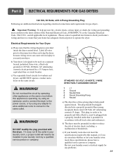
... the same circuit when this manual, or if you and your dryer. DO NOT modify the plug provided with the dryer. Important Warning: To help guard against shock. Part 6 ELECTRICAL REQUIREMENTS FOR GAS DRYERS 120 Volt, 60 Hertz, with 3-Prong Grounding Plug Following are uncertain ...problems. 19 Label all applicable local regulations. Do not overload the circuit by operating other appliances on the same circuit. ! b) The dryer must be plugged into a properly grounded three-prong receptacle that the wiring diagram is designed to be used on a separate branch, polarized,...
... the same circuit when this manual, or if you and your dryer. DO NOT modify the plug provided with the dryer. Important Warning: To help guard against shock. Part 6 ELECTRICAL REQUIREMENTS FOR GAS DRYERS 120 Volt, 60 Hertz, with 3-Prong Grounding Plug Following are uncertain ...problems. 19 Label all applicable local regulations. Do not overload the circuit by operating other appliances on the same circuit. ! b) The dryer must be plugged into a properly grounded three-prong receptacle that the wiring diagram is designed to be used on a separate branch, polarized,...


