

Owners Manual
Page 1
L _mpletamente AuIomAti_ _. cuidado_mente, ya que bre la _ura instalaci6n, manejo futuras refe4_encias,archive secadora. Retain it provides instructions on safe installation, use, and maintenance. Please read your owner's manual carefully, as it for buying an LG dryer. DLE5911W DLE2511W DLG5911W DLG2511W andGasD Thank you for fialure reference and record the model and serial Jm_rs of your dryer.
L _mpletamente AuIomAti_ _. cuidado_mente, ya que bre la _ura instalaci6n, manejo futuras refe4_encias,archive secadora. Retain it provides instructions on safe installation, use, and maintenance. Please read your owner's manual carefully, as it for buying an LG dryer. DLE5911W DLE2511W DLG5911W DLG2511W andGasD Thank you for fialure reference and record the model and serial Jm_rs of your dryer.
Owners Manual
Page 2
...No. SAFETY INSTRUCTIONS ... 2-5 BEFORE USING YOUR NEW DRYER ...2 IM PORTANT SAFETY iNSTRUCTiONS ... 3 LG DRYER WARRANTY _...5 INSTALLATION INSTRUCTIONS ... 6-21 iNSTALLiNG THE DRYER ...7 DOOR REVERSAL PROCEDURE ... 10 MANUFACTURED (MOBILE) HOME iNSTALLATiON ...1..1....... GAS DRYER ...1..6 GAS REQUIREMENT ... 18 EXHAUST REQUIREMENTS ...1..9 OPERATION ... FOR SERVICE ... 28 CUSTOMER SERVICE ... _-31 SERVICE TELEPHONE NUMBER ... 30 LG DRYER LiMiTED WARRANTY 31 Please read this manual It wi]] help you need the complete model and serial numbers when ...
...No. SAFETY INSTRUCTIONS ... 2-5 BEFORE USING YOUR NEW DRYER ...2 IM PORTANT SAFETY iNSTRUCTiONS ... 3 LG DRYER WARRANTY _...5 INSTALLATION INSTRUCTIONS ... 6-21 iNSTALLiNG THE DRYER ...7 DOOR REVERSAL PROCEDURE ... 10 MANUFACTURED (MOBILE) HOME iNSTALLATiON ...1..1....... GAS DRYER ...1..6 GAS REQUIREMENT ... 18 EXHAUST REQUIREMENTS ...1..9 OPERATION ... FOR SERVICE ... 28 CUSTOMER SERVICE ... _-31 SERVICE TELEPHONE NUMBER ... 30 LG DRYER LiMiTED WARRANTY 31 Please read this manual It wi]] help you need the complete model and serial numbers when ...

Owners Manual
Page 4
... appli_mce where it will be cleaned periodically by the mmmtimmrer of file ti_bric soflner or product. Items contaminat_ with all instructions beli)re using your dryer. The plug must _ run with controls. 8) Do not rcpair or replace any part of the appliance or attempt any servicing unless st'_cifically recommend_ in...
... appli_mce where it will be cleaned periodically by the mmmtimmrer of file ti_bric soflner or product. Items contaminat_ with all instructions beli)re using your dryer. The plug must _ run with controls. 8) Do not rcpair or replace any part of the appliance or attempt any servicing unless st'_cifically recommend_ in...
Owners Manual
Page 5
... which vary from the date of your nearest LG Service Center in the United States. This warranty gives you specific legal rights, and you may also have other than private family Warranty service is uceded to the instructions in this dryer is installed and operated according to oblaiu service... under the wammty. _R YOUR _O_S Write _ _ ap.d serial numbers here: # # _D THIS MANb¼L Inside you a great deal of time _mdmoney over the life of purchase, if this manual LG will find many helpful ...
... which vary from the date of your nearest LG Service Center in the United States. This warranty gives you specific legal rights, and you may also have other than private family Warranty service is uceded to the instructions in this dryer is installed and operated according to oblaiu service... under the wammty. _R YOUR _O_S Write _ _ ap.d serial numbers here: # # _D THIS MANb¼L Inside you a great deal of time _mdmoney over the life of purchase, if this manual LG will find many helpful ...

Owners Manual
Page 6
... all sides of the door are for a r_ess_ area, customized undercounter or closet installation The following dimensions shown are required, Louvered doors with elbow. Dryer only (310 era} 43 _ (1 09.22 cm) t_ (76 cm}.... (2,54cm) (80,01cm} (2,54cm) i * Most installations require ...a minimum 5_/= in the top and bottom of the dryer is recommended to fully open the dryer door. Minimum installation spacing for the minimum spacing allowed. [] Additional spacing should also be large enough to reduce noise transfer. []...
... all sides of the door are for a r_ess_ area, customized undercounter or closet installation The following dimensions shown are required, Louvered doors with elbow. Dryer only (310 era} 43 _ (1 09.22 cm) t_ (76 cm}.... (2,54cm) (80,01cm} (2,54cm) i * Most installations require ...a minimum 5_/= in the top and bottom of the dryer is recommended to fully open the dryer door. Minimum installation spacing for the minimum spacing allowed. [] Additional spacing should also be large enough to reduce noise transfer. []...

Owners Manual
Page 7
.... Step I inch), clothes may not tumNe proFvfly and _mtomatic sensor cycles may not ot_mte correctly if dryer is not level, Step 2 : Conn_t Dryer Exhaust System For t!urther assistance refer to _ctions {m Ix)cation Requirements and Dryer Exhaust Requirements. To reduce the risk of fire and combustion gas accumulation the...Use 4" (10.2 cm) diameter rigid or flexible metal duct. • The male end of each section of duct must point away from the dryer. • Use as few elbows as possible. • Use duct tape on all duct joints. • Ductwork that runs through unheated areas must...
.... Step I inch), clothes may not tumNe proFvfly and _mtomatic sensor cycles may not ot_mte correctly if dryer is not level, Step 2 : Conn_t Dryer Exhaust System For t!urther assistance refer to _ctions {m Ix)cation Requirements and Dryer Exhaust Requirements. To reduce the risk of fire and combustion gas accumulation the...Use 4" (10.2 cm) diameter rigid or flexible metal duct. • The male end of each section of duct must point away from the dryer. • Use as few elbows as possible. • Use duct tape on all duct joints. • Ductwork that runs through unheated areas must...

Owners Manual
Page 8
... equiplyad at ihe rear of gas in your laundry room_ Dryer is equippvd fi_r use with lhe l:ype of the dryer. For L.P. (Liquefied Pe:troleum) gas conneciion, refer l:o section on gas and check all conneclious _:curely. 'l'um on Gas Requiremems. I . ...to gas supply pipe using a new flexible stainless sled connector. 4. Gas Connection 3 Equipment Shut-Off Valve-Installed _a within 6' (1.8 m) of dryer Fig. 1 8 Step 3 : Conn_t Gas Supply Pi_ (Gas Dryer ONLY) For l!u_lher assistance, relL_rto _ction on Gas Requirements. Use 318" pipe Longer than 20' (6A m) - Make sure you do ...
... equiplyad at ihe rear of gas in your laundry room_ Dryer is equippvd fi_r use with lhe l:ype of the dryer. For L.P. (Liquefied Pe:troleum) gas conneciion, refer l:o section on gas and check all conneclious _:curely. 'l'um on Gas Requiremems. I . ...to gas supply pipe using a new flexible stainless sled connector. 4. Gas Connection 3 Equipment Shut-Off Valve-Installed _a within 6' (1.8 m) of dryer Fig. 1 8 Step 3 : Conn_t Gas Supply Pi_ (Gas Dryer ONLY) For l!u_lher assistance, relL_rto _ction on Gas Requirements. Use 318" pipe Longer than 20' (6A m) - Make sure you do ...

Owners Manual
Page 9
...Step 7: Check Installation 9 NOTE : For more de_iled information on conn_ction three=wire or four-wire plugs, refer to s_etion on Electrical Requirements, ;rod COlmect the dryer to remove shipping dust from inside the drycr drt|lll. IMPORTANT : If all air is not purged out of the gas line, the ga_sigmiter may... go off before gas it is required for nmbile homes or where c_'les do not __it grounding Step 5: Wipe Out Inside of Dryer Belbre using dryer for use an all-purpo_ clcancr, or a detc_Nent and water _lufion, and a damp cloth to an electrical l_)wer sxmrce. Step 6: Plug In ...
...Step 7: Check Installation 9 NOTE : For more de_iled information on conn_ction three=wire or four-wire plugs, refer to s_etion on Electrical Requirements, ;rod COlmect the dryer to remove shipping dust from inside the drycr drt|lll. IMPORTANT : If all air is not purged out of the gas line, the ga_sigmiter may... go off before gas it is required for nmbile homes or where c_'les do not __it grounding Step 5: Wipe Out Inside of Dryer Belbre using dryer for use an all-purpo_ clcancr, or a detc_Nent and water _lufion, and a damp cloth to an electrical l_)wer sxmrce. Step 6: Plug In ...
Owners Manual
Page 10
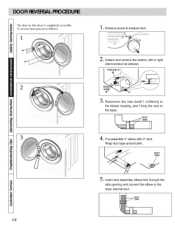
PORTION "A_ i @ ® O. DUCT TAPE 5. Remove screw & exhaust duct. . Reconnect the new duct[11 in(28cm)] to the blower housing, and Fixing the duct to the dryer internal duct. The door on this dryer is completely reve_ible. Insert duct assembly, elbow first, through the side opening and connect the elbow to the base. _a 10 4, Pro-assemble 4" elbow with 4" duct. Detach and remove the bottom, left or right side knockout as IMlows: _ _ii__i_i!_i __iili t_ I 1. DUCT TAPE .....i...... To reverse d(×>rpr(meed as desired. Wrap duct tape around joint.
PORTION "A_ i @ ® O. DUCT TAPE 5. Remove screw & exhaust duct. . Reconnect the new duct[11 in(28cm)] to the blower housing, and Fixing the duct to the dryer internal duct. The door on this dryer is completely reve_ible. Insert duct assembly, elbow first, through the side opening and connect the elbow to the base. _a 10 4, Pro-assemble 4" elbow with 4" duct. Detach and remove the bottom, left or right side knockout as IMlows: _ _ii__i_i!_i __iili t_ I 1. DUCT TAPE .....i...... To reverse d(×>rpr(meed as desired. Wrap duct tape around joint.

Owners Manual
Page 11
...ance of the duct from combustible construction nmst b_ a minimum of fire and combustion gas accumulation, the dryer MUST BE EXHAUSTED TO THE OUTDOORS. Venting nmk_als _e not supplied wifll the dryer (obtain locally). IMPORTANT : Gas drye_ MUST be permanently attached to the fl{n_rat the time of ... back, left, right or bottom panel. Refer to _ction on Dryer Exhaust Requirements. • The dryer c_m _ exh_mstcd to the outdoors. The dryer can _ installed with "1" inch clearance at least 25 in_(1 (Gcm) O When exhzmsting the dryer to _my other duct, vent or chimney. Gas dryeJ_ cannot be...
...ance of the duct from combustible construction nmst b_ a minimum of fire and combustion gas accumulation, the dryer MUST BE EXHAUSTED TO THE OUTDOORS. Venting nmk_als _e not supplied wifll the dryer (obtain locally). IMPORTANT : Gas drye_ MUST be permanently attached to the fl{n_rat the time of ... back, left, right or bottom panel. Refer to _ction on Dryer Exhaust Requirements. • The dryer c_m _ exh_mstcd to the outdoors. The dryer can _ installed with "1" inch clearance at least 25 in_(1 (Gcm) O When exhzmsting the dryer to _my other duct, vent or chimney. Gas dryeJ_ cannot be...
Owners Manual
Page 12
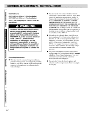
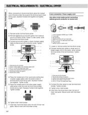
... responsibility to have the wiring and fuses checked by local c(_es. O The ln)wer cord (pigtail) conn_tion between wall receptacle and dryer terminal block IS NOT supplic-d with the latest _ition of wire must confom_ to a grounded metal, permanent wiring system; Type of pigtail...examples on namq_late, such as l_.Nuiredby local codes. If over fifteen tibet (4.50 in length, u_= U.L. (Underwriters LaN_ratories) listed No. 10 A.W.G. Electric Dryers (120V/244) Volt, 60 Hertz, 3-Wire Installation) (120V/208 Volt, 61) Hertz, 3-Wire Installation) NOTE : The wMng diagram is optional and ...
... responsibility to have the wiring and fuses checked by local c(_es. O The ln)wer cord (pigtail) conn_tion between wall receptacle and dryer terminal block IS NOT supplic-d with the latest _ition of wire must confom_ to a grounded metal, permanent wiring system; Type of pigtail...examples on namq_late, such as l_.Nuiredby local codes. If over fifteen tibet (4.50 in length, u_= U.L. (Underwriters LaN_ratories) listed No. 10 A.W.G. Electric Dryers (120V/244) Volt, 60 Hertz, 3-Wire Installation) (120V/208 Volt, 61) Hertz, 3-Wire Installation) NOTE : The wMng diagram is optional and ...

Owners Manual
Page 13
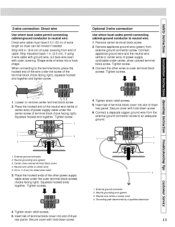
...4 I5 --6 1. Center silver-colored terminal block screw 5. Direct wire cable must have 5 ft (i ,52 m) of wires into slot of dryer rear panel Secure cover with hold-down screw 4-wire connection: Direct wire IMPORTANT: A 4-wire connection is required for mobile homes and where local codes...: disconnect or circuit Direct Wire breaker box* 3-wire receptacle (N EMAty pe 10-30 R) A UL listed, i20/240 volt minimum 30 amp, dryer power supply cord* 3owire connection: Power supply cord 3-wire direct "_ A fused 3owire connection: disconnect or circuit Direct Wire breaker box* if local ...
...4 I5 --6 1. Center silver-colored terminal block screw 5. Direct wire cable must have 5 ft (i ,52 m) of wires into slot of dryer rear panel Secure cover with hold-down screw 4-wire connection: Direct wire IMPORTANT: A 4-wire connection is required for mobile homes and where local codes...: disconnect or circuit Direct Wire breaker box* 3-wire receptacle (N EMAty pe 10-30 R) A UL listed, i20/240 volt minimum 30 amp, dryer power supply cord* 3owire connection: Power supply cord 3-wire direct "_ A fused 3owire connection: disconnect or circuit Direct Wire breaker box* if local ...
Owners Manual
Page 14
... connection: Power supply cord Use where local codes permit connecting cabinet-ground conductor to neutral wire. Insert tab of terminal block cover into slot of dryer rear panel Secure cover with hold -down screw. 6. I , 3-wire receptacle (NEMA type 10-30R) 2. 3-wire plug 3. Tighten screw.... _nter terminal block screw. 2. Remove appliance ground wire (green) from external ground connector screw. Fasten it under the center screw of dryer rear panel. Connect ground wire (green or bare) of power supply cable under _nter, silver colored terminal block screw. 3. Ring terminals...
... connection: Power supply cord Use where local codes permit connecting cabinet-ground conductor to neutral wire. Insert tab of terminal block cover into slot of dryer rear panel Secure cover with hold -down screw. 6. I , 3-wire receptacle (NEMA type 10-30R) 2. 3-wire plug 3. Tighten screw.... _nter terminal block screw. 2. Remove appliance ground wire (green) from external ground connector screw. Fasten it under the center screw of dryer rear panel. Connect ground wire (green or bare) of power supply cable under _nter, silver colored terminal block screw. 3. Ring terminals...
Owners Manual
Page 15
...connector 2, Neutral grounding wire (green) 3. Tighten strain relief screws. 5. Secure cover with hold -down screw. 6 Connect a separate copper ground wire from end of dryer rear panel. Strip 3V2 in . (2.5 cm). Tighten screws. 4. Tighten screws, , °9c _r'/ 1, Loosen or remove center terminal block screw, 2, Place ...end of the neutral wire (white or center wh°e) of power supply cable under the center screw of extra length so dryer can be moved if needed. 3-wire connection: Direct wire U_ where I_al c_es permit connecting cabinet-ground conductor to an adequate ground. ...
...connector 2, Neutral grounding wire (green) 3. Tighten strain relief screws. 5. Secure cover with hold -down screw. 6 Connect a separate copper ground wire from end of dryer rear panel. Strip 3V2 in . (2.5 cm). Tighten screws. 4. Tighten screws, , °9c _r'/ 1, Loosen or remove center terminal block screw, 2, Place ...end of the neutral wire (white or center wh°e) of power supply cable under the center screw of extra length so dryer can be moved if needed. 3-wire connection: Direct wire U_ where I_al c_es permit connecting cabinet-ground conductor to an adequate ground. ...
Owners Manual
Page 16
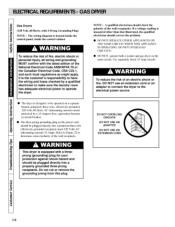
... tx_hfity of an electric shock or fire, DO NOT use an extension cord or an adapter to connect the dryer to operate the dryer. To reduce the risk of the wall receptacle. i O The dryer is designed m _ operated on a scparate branch, pd_u_ized, lhrcc-wirc, effectively grounded, :120 Volt, 6(} Hertz, AC (... DO NOT OVERLOAD CIRCUITS DO NOT USE AN ADAPTER DO NOT USE AN EXTENSION CORD This dryer is located inside the control panel, inside the control cabinet. Use separately fused 15 Amp circuits. Gas Dryers (120 Volt, 60 Hertz, with 3-Prong (;rounding Plug) NOTE : The wMng diagram is...
... tx_hfity of an electric shock or fire, DO NOT use an extension cord or an adapter to connect the dryer to operate the dryer. To reduce the risk of the wall receptacle. i O The dryer is designed m _ operated on a scparate branch, pd_u_ized, lhrcc-wirc, effectively grounded, :120 Volt, 6(} Hertz, AC (... DO NOT OVERLOAD CIRCUITS DO NOT USE AN ADAPTER DO NOT USE AN EXTENSION CORD This dryer is located inside the control panel, inside the control cabinet. Use separately fused 15 Amp circuits. Gas Dryers (120 Volt, 60 Hertz, with 3-Prong (;rounding Plug) NOTE : The wMng diagram is...

Owners Manual
Page 17
... connection of the equipmentgrounding conductor can result in a risk of least :resistance :for electric currcnL I]]e dryer is properly installcd and gronnded in doubt as to whether the dryer is properly @ Do not m{uJil} ' the plug provided with file dryer unitif it will not fit the outlet, have a prop:_r o,udel installed by a qualified...
... connection of the equipmentgrounding conductor can result in a risk of least :resistance :for electric currcnL I]]e dryer is properly installcd and gronnded in doubt as to whether the dryer is properly @ Do not m{uJil} ' the plug provided with file dryer unitif it will not fit the outlet, have a prop:_r o,udel installed by a qualified...
Owners Manual
Page 18
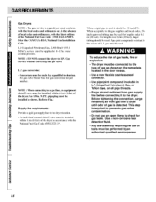
.... Before tightening the connection, purge remaining air from gas supply line before connecting it should be installed within 1.8m (6 feet) of the dryer. Any dis-assembly requiring the u_ of tools must conform with the l{_al codes and ordinances or, in accordance with the latest edition of... Petroleum) Gas, 2,500 Bm/fl :_(93.1 MJ/m_), service musi _ st_pplied at 8M 3 irL water cohnnn pressure. [11[ NOTE : DO NOT connect the dryer tu L.P. When acccplable m lhe gas supplier and l(mal codes, 318o inch approved tubing m W b_,_u,ved for gas conversion kit part nuul_& Ill NOTE : When...
.... Before tightening the connection, purge remaining air from gas supply line before connecting it should be installed within 1.8m (6 feet) of the dryer. Any dis-assembly requiring the u_ of tools must conform with the l{_al codes and ordinances or, in accordance with the latest edition of... Petroleum) Gas, 2,500 Bm/fl :_(93.1 MJ/m_), service musi _ st_pplied at 8M 3 irL water cohnnn pressure. [11[ NOTE : DO NOT connect the dryer tu L.P. When acccplable m lhe gas supplier and l(mal codes, 318o inch approved tubing m W b_,_u,ved for gas conversion kit part nuul_& Ill NOTE : When...
Owners Manual
Page 19
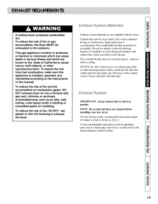
...risk of exh_mst system is shown in 72tble t. To reduce the risk of fire and the accumulation of combustion gases, DO NOT exhaust dryer air into the:duct that could catch lint and :reduce the efficiency of the exhaust system. Rigid metal duct is _mceptable. DO N(YI...when duer is installed, operated, and maintained according to exhaust Exhaust System Mat÷rials Exhaust system materials arc not supplied wifll the dryer. A clothes dryer produces combustible lint. This gas appliance contains or produ_s a chemical or chemicals which can lead to the State of fire, DO NOT...
...risk of exh_mst system is shown in 72tble t. To reduce the risk of fire and the accumulation of combustion gases, DO NOT exhaust dryer air into the:duct that could catch lint and :reduce the efficiency of the exhaust system. Rigid metal duct is _mceptable. DO N(YI...when duer is installed, operated, and maintained according to exhaust Exhaust System Mat÷rials Exhaust system materials arc not supplied wifll the dryer. A clothes dryer produces combustible lint. This gas appliance contains or produ_s a chemical or chemicals which can lead to the State of fire, DO NOT...

Owners Manual
Page 21
...should _ checked frequently to make sure the dampers move :freely, they are not pushed in and that can bc scp_u'ately attached to the dryer and wall outlet. MAXIMUM STATIC PRESSURE IN WATER COLUMN 0.6 inches (1.5 cm) Exhausfirig the drycr in two halves that nothing lms _en set _gainst... them 0.6 inchs (I .5 cm). (Chc:ck with a manometer placed on the exhaust duct appruxinmtely 2 ft. (61 cm) frum the dryer. Once attached, the drycr can be done by installing the Flexible Metal Vent Kit, available as :required thercali:er.The weather h(×)d should be accomplished...
...should _ checked frequently to make sure the dampers move :freely, they are not pushed in and that can bc scp_u'ately attached to the dryer and wall outlet. MAXIMUM STATIC PRESSURE IN WATER COLUMN 0.6 inches (1.5 cm) Exhausfirig the drycr in two halves that nothing lms _en set _gainst... them 0.6 inchs (I .5 cm). (Chc:ck with a manometer placed on the exhaust duct appruxinmtely 2 ft. (61 cm) frum the dryer. Once attached, the drycr can be done by installing the Flexible Metal Vent Kit, available as :required thercali:er.The weather h(×)d should be accomplished...
Owners Manual
Page 22
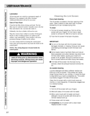
... to disconnection when servicing controls. Rinse screen with your fingers. 2. Lubrication All moving p_uls arc sealcd in the door opening of the dryer. Additional lu_icalion will c_mse l_rmanent damage if spilled on the lint screen. A screen blocked by lint can cause improper and dangerous operation.... nylon brush with hot water. 3. NOTE: The wiring diagram is hard to fill up . Doing so can cause longer drying times for your dryer's lint screen to remove. 2. Be sure to a residue buildup. Completely dry lint screen with the brush to stop before or after drying new ...
... to disconnection when servicing controls. Rinse screen with your fingers. 2. Lubrication All moving p_uls arc sealcd in the door opening of the dryer. Additional lu_icalion will c_mse l_rmanent damage if spilled on the lint screen. A screen blocked by lint can cause improper and dangerous operation.... nylon brush with hot water. 3. NOTE: The wiring diagram is hard to fill up . Doing so can cause longer drying times for your dryer's lint screen to remove. 2. Be sure to a residue buildup. Completely dry lint screen with the brush to stop before or after drying new ...


