

Owners Manual
Page 4
... plug must _ run with all instructions beli)re using your dryer. Alternatively, an equipmentgr(mnding conductor must _ plumed iuto an appropria|e ou|let that could ignite or expk_de. 3) Do not allow chil&'en to the equipment-grounding terminal or lead on or in accordalme with the circuit conductors and connected to...
... plug must _ run with all instructions beli)re using your dryer. Alternatively, an equipmentgr(mnding conductor must _ plumed iuto an appropria|e ou|let that could ignite or expk_de. 3) Do not allow chil&'en to the equipment-grounding terminal or lead on or in accordalme with the circuit conductors and connected to...

Owners Manual
Page 9
...¢_ and labeled a:ssuitable for the fi_t timc, use in a clothes dryer. If this happens, aher approximately two minutes the igniter will ignite. Heat Source Check El_tric Dryers Close the loading door and start the dryer in a heat _tting (rct;cr to the Operating Instructions...perating Inslructions suppli_ with the dryer); NOTE : Four-wire cord is ignited. Step 7: Check Installation 9 Gas Dryers Close the loading door, start , the igniter will glow red and the main burner will ag_n attempt ga_ ignition. After the d_'cr has operated l;:_rfllree minutes, the exhaust air...
...¢_ and labeled a:ssuitable for the fi_t timc, use in a clothes dryer. If this happens, aher approximately two minutes the igniter will ignite. Heat Source Check El_tric Dryers Close the loading door and start the dryer in a heat _tting (rct;cr to the Operating Instructions...perating Inslructions suppli_ with the dryer); NOTE : Four-wire cord is ignited. Step 7: Check Installation 9 Gas Dryers Close the loading door, start , the igniter will glow red and the main burner will ag_n attempt ga_ ignition. After the d_'cr has operated l;:_rfllree minutes, the exhaust air...
Service Manual
Page 12
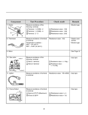
...Ω Resistance value : 20Ω Remark • Electric type Measure resistance of terminal to terminal Resistance value : 100~800Ω • Gas type 12. Thermistor 9. Igniter valve 2 Measure resistance of the following terminal Valve 1 terminal Valve 2 terminal • Gas type Resistance value : > 1.5kg ~ Resistance value : > 1.5~2.5kg 11. Component 7. Motor Test Procedure...
...Ω Resistance value : 20Ω Remark • Electric type Measure resistance of terminal to terminal Resistance value : 100~800Ω • Gas type 12. Thermistor 9. Igniter valve 2 Measure resistance of the following terminal Valve 1 terminal Valve 2 terminal • Gas type Resistance value : > 1.5kg ~ Resistance value : > 1.5~2.5kg 11. Component 7. Motor Test Procedure...
Service Manual
Page 24
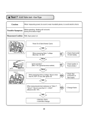
... 90V? Measurement Condition With dryer power on "Valve 1", "Valve 2", Value is more than1.5 ~ 2.5kΩ? (Measure after Igniter off) YES NO • Check Gas connection or Gas supply When measuring terminal resistance on Valve 1 Igniter Valve 2 Power On & Start (Normal Cycle) NO When measuring Valve 1 voltage, More than AC 90V? (10 sec...
... 90V? Measurement Condition With dryer power on "Valve 1", "Valve 2", Value is more than1.5 ~ 2.5kΩ? (Measure after Igniter off) YES NO • Check Gas connection or Gas supply When measuring terminal resistance on Valve 1 Igniter Valve 2 Power On & Start (Normal Cycle) NO When measuring Valve 1 voltage, More than AC 90V? (10 sec...
Service Manual
Page 26
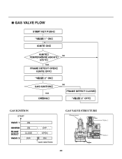
GAS VALVE FLOW START KEY PUSH "VALVE 1" ON IGNITE ON IGNITE TEMPERATURE ABOUT 370"F YES FRAME DETECT OPEN IGNITE OFF "VALVE 2" ON GAS IGNITION YES DRYING NO NO FRAME DETECT CLOSE "VALVE 2" OFF GAS IGNITION START VALVE 1 IGNITER FRAME DETECT VALVE 2 ON ON CLOSE OFF OFF OPEN ON GAS IGNITION GAS VALVE STRUCTURE 25
GAS VALVE FLOW START KEY PUSH "VALVE 1" ON IGNITE ON IGNITE TEMPERATURE ABOUT 370"F YES FRAME DETECT OPEN IGNITE OFF "VALVE 2" ON GAS IGNITION YES DRYING NO NO FRAME DETECT CLOSE "VALVE 2" OFF GAS IGNITION START VALVE 1 IGNITER FRAME DETECT VALVE 2 ON ON CLOSE OFF OFF OPEN ON GAS IGNITION GAS VALVE STRUCTURE 25


