
Service Manual
Page 11
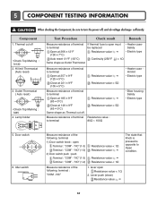
...; • Electric type Auto reset -31°F (-35°C) Continuity (250°F ) < 1Ω Same shape as Thermal cut off . Outlet Thermostat ( Auto reset) • Check Top Marking : N85 4. Door switch 6. "NO" (1-2) Resistance value < 1Ω Resistance value ∞ Resistance value ... CAUTION When checking the Component, be replaced Safety Open at 149 ± 9°F (65 ± 5°C) Same shape as Outlet Thermostat. Component 1. NC" 1. "NC" (1-3) Terminal : "COM" - Lamp holder Test Procedure Check result Remark Measure resistance of the following terminal...
...; • Electric type Auto reset -31°F (-35°C) Continuity (250°F ) < 1Ω Same shape as Thermal cut off . Outlet Thermostat ( Auto reset) • Check Top Marking : N85 4. Door switch 6. "NO" (1-2) Resistance value < 1Ω Resistance value ∞ Resistance value ... CAUTION When checking the Component, be replaced Safety Open at 149 ± 9°F (65 ± 5°C) Same shape as Outlet Thermostat. Component 1. NC" 1. "NC" (1-3) Terminal : "COM" - Lamp holder Test Procedure Check result Remark Measure resistance of the following terminal...

Service Manual
Page 13
... reset) • Check Top Marking : N95 13. Component 13. Outlet Thermostat (Manual reset) • Check Top Marking : N100 Test Procedure Measure resistance of terminal to terminal Open at 203 ± 7°F (95 ± 5°C) Close at ...
... reset) • Check Top Marking : N95 13. Component 13. Outlet Thermostat (Manual reset) • Check Top Marking : N100 Test Procedure Measure resistance of terminal to terminal Open at 203 ± 7°F (95 ± 5°C) Close at ...
Service Manual
Page 17
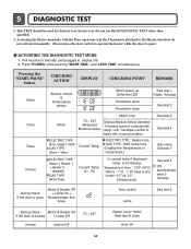
... sound See test 3 See test 4 Gas valve See test 7 See test 5 Off automatically after 5 minutes During check, If the door is open may trip the Thermostat attached to the Heater, therefore do not activate it manually. (Do not press the door switch to operate the heater while the door is contacted...
... sound See test 3 See test 4 Gas valve See test 7 See test 5 Off automatically after 5 minutes During check, If the door is open may trip the Thermostat attached to the Heater, therefore do not activate it manually. (Do not press the door switch to operate the heater while the door is contacted...
Service Manual
Page 20
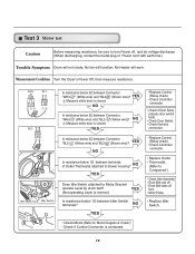
.... • Check Harness connection. NO YES • Replace Control. (Relay check) • Check Controller connector. • Replace Outlet • Thermostat. (Refer to 'Component') • Check Idler Assembly. • Drum Belt cuts off • Drum Belt takes off , and do voltage discharge.... (When discharging, contact the metal plug of Outlet Thermostat attached to blower housing? Measurement Condition Turn the Dryer's Power Off, then measure resistance. " (White wire) and "BL2- " (White wire...
.... • Check Harness connection. NO YES • Replace Control. (Relay check) • Check Controller connector. • Replace Outlet • Thermostat. (Refer to 'Component') • Check Idler Assembly. • Drum Belt cuts off • Drum Belt takes off , and do voltage discharge.... (When discharging, contact the metal plug of Outlet Thermostat attached to blower housing? Measurement Condition Turn the Dryer's Power Off, then measure resistance. " (White wire) and "BL2- " (White wire...
Service Manual
Page 23
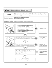
...and at RUN condition. • Check Motor and replace it. NO • Replace Heater. NO YES • Replace TH2 (Safety Thermostat). Check Motor. YES Check if the value of Power cord with earth line.) Trouble Symptom While operating, Heating will not work. Measurement ... (When discharging, contact the metal plug of measured resistance is below 18 ~ 22Ω? 2. Is resistance between terminal TH2 (Safety Thermostat). Check Harness-linking Connector. 22 TH3 TH2 1. Is resistance between Heater terminal and below 9 ~ 11Ω? NO YES • Replace TH3...
...and at RUN condition. • Check Motor and replace it. NO • Replace Heater. NO YES • Replace TH2 (Safety Thermostat). Check Motor. YES Check if the value of Power cord with earth line.) Trouble Symptom While operating, Heating will not work. Measurement ... (When discharging, contact the metal plug of measured resistance is below 18 ~ 22Ω? 2. Is resistance between terminal TH2 (Safety Thermostat). Check Harness-linking Connector. 22 TH3 TH2 1. Is resistance between Heater terminal and below 9 ~ 11Ω? NO YES • Replace TH3...
Service Manual
Page 24
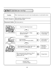
... work. Test 7 GAS Valve test - Gas Type Caution When measuring power, be sure to wear insulated gloves, to avoid electric shock. YES NO • Check thermostat Hi limit Safety Igniter operates? (after 1 min, Igniter becomes reddish) YES NO • Check Igniter & Frame detect When measuring Valve 2 voltage, Value is more than...
... work. Test 7 GAS Valve test - Gas Type Caution When measuring power, be sure to wear insulated gloves, to avoid electric shock. YES NO • Check thermostat Hi limit Safety Igniter operates? (after 1 min, Igniter becomes reddish) YES NO • Check Igniter & Frame detect When measuring Valve 2 voltage, Value is more than...


