
Owners Manual
Page 1
...;/월/일 PREPARED APPROVED 시방자 승인자 > 1 2 FILM에 준함. 3 4 5 LG(63)-A-5501-34 > 1. No. Exterier size on LG design film. 3. DWG. 가 나 P/NO. 다 3828EL3003M SEC. 가 WORK BRAND 나 MODEL 다... INTERIER MATERIAL AND PRINTING DESCRIPTION LG MODEL 명 DLE9577WM / DLG9588WM M LG DLE9577SM / DLG9588SM 3828EL3003M 1 1 SNOW WHITE 100g OFFSET 인쇄 - Before product controlled by criteria sample. 5. The part should not contain prohibited substances(Pb...
...;/월/일 PREPARED APPROVED 시방자 승인자 > 1 2 FILM에 준함. 3 4 5 LG(63)-A-5501-34 > 1. No. Exterier size on LG design film. 3. DWG. 가 나 P/NO. 다 3828EL3003M SEC. 가 WORK BRAND 나 MODEL 다... INTERIER MATERIAL AND PRINTING DESCRIPTION LG MODEL 명 DLE9577WM / DLG9588WM M LG DLE9577SM / DLG9588SM 3828EL3003M 1 1 SNOW WHITE 100g OFFSET 인쇄 - Before product controlled by criteria sample. 5. The part should not contain prohibited substances(Pb...
Owners Manual
Page 4
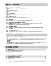
... more or less drying is not a malfunction. TABLE OF CONTENTS PART 1. INITIAL STEPS FOR INSTALLING YOUR DRYER ...7 PART 4. ACCESSORIES INSTALLATION ...15 PART 5. IMPORTANT WARRANTY AND SAFETY INSTRUCTIONS ...4 PART 3. OPERATING YOUR DRYER ...25 PART 10. You might see a sudden increase or decrease in the ...operating the dryer easy. 6 USING THE RLM (REMOTE LAUNDRY MONITOR) The RLM monitors status of your home. TROUBLESHOOTING GUIDE...31 LG DRYER LIMITED WARRANTY...34 2 PRODUCT FEATURES 1 OUTSTANDING PERFORMANCE Besides the large capacity, you like them at the end of the...
... more or less drying is not a malfunction. TABLE OF CONTENTS PART 1. INITIAL STEPS FOR INSTALLING YOUR DRYER ...7 PART 4. ACCESSORIES INSTALLATION ...15 PART 5. IMPORTANT WARRANTY AND SAFETY INSTRUCTIONS ...4 PART 3. OPERATING YOUR DRYER ...25 PART 10. You might see a sudden increase or decrease in the ...operating the dryer easy. 6 USING THE RLM (REMOTE LAUNDRY MONITOR) The RLM monitors status of your home. TROUBLESHOOTING GUIDE...31 LG DRYER LIMITED WARRANTY...34 2 PRODUCT FEATURES 1 OUTSTANDING PERFORMANCE Besides the large capacity, you like them at the end of the...
Owners Manual
Page 5
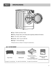
See page 16 for instructions. See page 15 for instructions. 3 Part 1 SPECIFICATIONS ■ Type : Electric and Gas Dryer ■ Rating : Please refer to the rating label regarding detailed information. ■ Size : 27 x 30.1 x 38.7 inches ■ ...
See page 16 for instructions. See page 15 for instructions. 3 Part 1 SPECIFICATIONS ■ Type : Electric and Gas Dryer ■ Rating : Please refer to the rating label regarding detailed information. ■ Size : 27 x 30.1 x 38.7 inches ■ ...
Owners Manual
Page 6
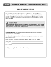
...contacting service. 4 Use the space below to prevent property damage, personal injury, or death when using your new LG dryer. You will repair or replace any parts defective in this manual. Model Number. WARNING! To reduce the risk of fire or explosion, electric shock or ..., the recommendations in material or workmanship throughout the warranty period, beginning with the date of your appliance follow basic precautions. Part 2 IMPORTANT WARRANTY AND SAFETY INSTRUCTIONS SEEKING WARRANTY SERVICE The warranty for only 90 days. Warranty Service is subjected to the instructions ...
...contacting service. 4 Use the space below to prevent property damage, personal injury, or death when using your new LG dryer. You will repair or replace any parts defective in this manual. Model Number. WARNING! To reduce the risk of fire or explosion, electric shock or ..., the recommendations in material or workmanship throughout the warranty period, beginning with the date of your appliance follow basic precautions. Part 2 IMPORTANT WARRANTY AND SAFETY INSTRUCTIONS SEEKING WARRANTY SERVICE The warranty for only 90 days. Warranty Service is subjected to the instructions ...
Owners Manual
Page 7
...having an equipment-grounding conductor and a grounding plug. Do not modify the plug provided with controls. 8) Do not repair or replace any part of the appliance or attempt any risk of children is necessary when using the appliance. 2) Do not dry articles that could ignite or...path of malfunction or breakdown, grounding will not fit the outlet, have come into the appliance if the drum is properly grounded. Part 2 IMPORTANT WARRANTY AND SAFETY INSTRUCTIONS IMPORTANT SAFETY INSTRUCTIONS ! To help reduce any servicing unless specifically recommended in your dryer, please exercise...
...having an equipment-grounding conductor and a grounding plug. Do not modify the plug provided with controls. 8) Do not repair or replace any part of the appliance or attempt any risk of children is necessary when using the appliance. 2) Do not dry articles that could ignite or...path of malfunction or breakdown, grounding will not fit the outlet, have come into the appliance if the drum is properly grounded. Part 2 IMPORTANT WARRANTY AND SAFETY INSTRUCTIONS IMPORTANT SAFETY INSTRUCTIONS ! To help reduce any servicing unless specifically recommended in your dryer, please exercise...
Owners Manual
Page 8
... not try to such substances. Gas appliances can result in your building. • Clear the room, building or area of natural gas or LP fuels. Part 2 IMPORTANT WARRANTY AND SAFETY INSTRUCTIONS !
... not try to such substances. Gas appliances can result in your building. • Clear the room, building or area of natural gas or LP fuels. Part 2 IMPORTANT WARRANTY AND SAFETY INSTRUCTIONS !
Owners Manual
Page 9
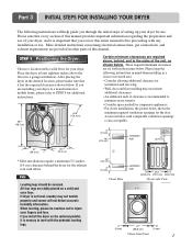
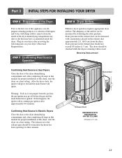
...concerning electrical connections, gas connections, and exhaust requirements are set forth in the picture below. Those required minimum clearances are provided in other parts of clearance is recommended to STEP 9 for additional instructions. 38.7" (98.3 cm) 49.8" (126.4 cm) Certain minimum clearances are... location, please make sure that every section of this entire manual before proceeding with a solid floor for your fingers and toes. Part 3 INITIAL STEPS FOR INSTALLING YOUR DRYER The following instructions in mind when installing in a closet or recessed area: • Consider...
...concerning electrical connections, gas connections, and exhaust requirements are set forth in the picture below. Those required minimum clearances are provided in other parts of clearance is recommended to STEP 9 for additional instructions. 38.7" (98.3 cm) 49.8" (126.4 cm) Certain minimum clearances are... location, please make sure that every section of this entire manual before proceeding with a solid floor for your fingers and toes. Part 3 INITIAL STEPS FOR INSTALLING YOUR DRYER The following instructions in mind when installing in a closet or recessed area: • Consider...
Owners Manual
Page 10
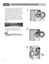
... the center when closed. 1 2 3 8 The maximum slope of and clearances for Reversing the Door The door on the floor and the dryer should not rock. Part 3 INITIAL STEPS FOR INSTALLING YOUR DRYER Once in which your door opens: Note Door and latch should be installed to open either to the left...
... the center when closed. 1 2 3 8 The maximum slope of and clearances for Reversing the Door The door on the floor and the dryer should not rock. Part 3 INITIAL STEPS FOR INSTALLING YOUR DRYER Once in which your door opens: Note Door and latch should be installed to open either to the left...
Owners Manual
Page 11
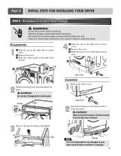
If not, the dryer may not operate. 3 Remove the plate by lifting it clicks into place. ! Part 3 INITIAL STEPS FOR INSTALLING YOUR DRYER STEP 3 Procedure of control panel. ⚧ Remove the screw. ⚨ Slide the control panel to the right about an .... Disassemble 1 ⚦ Push the cap on the right side of Control Panel Change ! Make sure that the housing is changing. 9 WARNING! Plate Frame Note Housing LG is not responsible for any damages to follow these instructions can result in death or electrical shock. Housing Hook Frame 4 ⚦ Push the cap on...
If not, the dryer may not operate. 3 Remove the plate by lifting it clicks into place. ! Part 3 INITIAL STEPS FOR INSTALLING YOUR DRYER STEP 3 Procedure of control panel. ⚧ Remove the screw. ⚨ Slide the control panel to the right about an .... Disassemble 1 ⚦ Push the cap on the right side of Control Panel Change ! Make sure that the housing is changing. 9 WARNING! Plate Frame Note Housing LG is not responsible for any damages to follow these instructions can result in death or electrical shock. Housing Hook Frame 4 ⚦ Push the cap on...
Owners Manual
Page 12
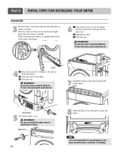
... in the holes of the frame. 8 Slide the plate to the right. ⚨ Close the cap. ! Part 3 INITIAL STEPS FOR INSTALLING YOUR DRYER Assemble 3 Put the hooks of the panel into place. WARNING! Note LG is changing. Be sure the screw is properly tightened. Be sure the screw is properly tightened. Then...
... in the holes of the frame. 8 Slide the plate to the right. ⚨ Close the cap. ! Part 3 INITIAL STEPS FOR INSTALLING YOUR DRYER Assemble 3 Put the hooks of the panel into place. WARNING! Note LG is changing. Be sure the screw is properly tightened. Be sure the screw is properly tightened. Then...
Owners Manual
Page 13
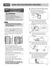
... to manual section on pipe walls. • PLEASE BE AWARE THAT FAILURE TO EXHAUST THE DRYER CORRECTLY WILL VOID THE DRYER'S WARRANTY. 3-1. Part 3 INITIAL STEPS FOR INSTALLING YOUR DRYER STEP 3 Connecting the Exhaust and Venting System. ! Please follow these instructions can result in order to ...short piece of a short duct. In addition to the following warnings, please refer to the outside. Remove screw and exhaust duct. (Use exhaust kit part #3911EZ9131X.) 2-1. IMPORTANT: To reduce the risk of exhaust duct must point away from the dryer. • Use as few elbow joints as possible...
... to manual section on pipe walls. • PLEASE BE AWARE THAT FAILURE TO EXHAUST THE DRYER CORRECTLY WILL VOID THE DRYER'S WARRANTY. 3-1. Part 3 INITIAL STEPS FOR INSTALLING YOUR DRYER STEP 3 Connecting the Exhaust and Venting System. ! Please follow these instructions can result in order to ...short piece of a short duct. In addition to the following warnings, please refer to the outside. Remove screw and exhaust duct. (Use exhaust kit part #3911EZ9131X.) 2-1. IMPORTANT: To reduce the risk of exhaust duct must point away from the dryer. • Use as few elbow joints as possible...
Owners Manual
Page 14
.... • Use a UL approved strain relief. • Disconnect power before taking any problem with the BTU rating at the elevations up to 10,000 feet. Part 3 INITIAL STEPS FOR INSTALLING YOUR DRYER STEP 4 Connection of gas you have any steps to install or use this manual's section entitled Gas Requirements and... input setting is located at this manual's section on Gas Requirements and Instructions. 1 2 5 3 4 1. If your house is not needed , orifice conversion should be connected to Part 7 (page 20) 5.
.... • Use a UL approved strain relief. • Disconnect power before taking any problem with the BTU rating at the elevations up to 10,000 feet. Part 3 INITIAL STEPS FOR INSTALLING YOUR DRYER STEP 4 Connection of gas you have any steps to install or use this manual's section entitled Gas Requirements and... input setting is located at this manual's section on Gas Requirements and Instructions. 1 2 5 3 4 1. If your house is not needed , orifice conversion should be connected to Part 7 (page 20) 5.
Owners Manual
Page 15
... dryer starts, the igniter will glow red and the main burner will re-attempt gas ignition after reviewing the following parts on a heat setting. Static pressure in your dryer's Electrical Requirements. Part 3 INITIAL STEPS FOR INSTALLING YOUR DRYER STEP 6 Preparation of the dryer drum/drying compartment any dust or dirt that may...
... dryer starts, the igniter will glow red and the main burner will re-attempt gas ignition after reviewing the following parts on a heat setting. Static pressure in your dryer's Electrical Requirements. Part 3 INITIAL STEPS FOR INSTALLING YOUR DRYER STEP 6 Preparation of the dryer drum/drying compartment any dust or dirt that may...
Owners Manual
Page 16
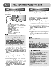
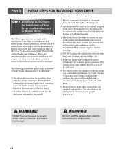
Part 3 INITIAL STEPS FOR INSTALLING YOUR DRYER STEP 9 Additional Instructions for Installation of combustion and fire, the dryer must be vented to the outside. 3) Electric dryers ... an electric dryer must comply with the dryer. The following instructions are not supplied with the Manufactured Home Construction and Safety Standards Title 24 CFR, Part 32-80 or Standard CAN/CSA0Z240 MH and local codes and ordinances. The following instructions apply to ensure proper operation. You should obtain the venting...
Part 3 INITIAL STEPS FOR INSTALLING YOUR DRYER STEP 9 Additional Instructions for Installation of combustion and fire, the dryer must be vented to the outside. 3) Electric dryers ... an electric dryer must comply with the dryer. The following instructions are not supplied with the Manufactured Home Construction and Safety Standards Title 24 CFR, Part 32-80 or Standard CAN/CSA0Z240 MH and local codes and ordinances. The following instructions apply to ensure proper operation. You should obtain the venting...
Owners Manual
Page 17
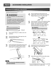
Part 4 ACCESSORIES INSTALLATION Stacking Kit Installation Instructions To ensure safe and secure installation, please observe the instructions below. ! This procedure should be careful not to the ...
Part 4 ACCESSORIES INSTALLATION Stacking Kit Installation Instructions To ensure safe and secure installation, please observe the instructions below. ! This procedure should be careful not to the ...
Owners Manual
Page 18
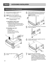
for washer/ combo for dryer 5 6 3 for dryer for washer/ combo 7 16 Part 4 ACCESSORIES INSTALLATION Pedestal Installation Instructions 1 4 2 1) Shut off gas. 2) Unplug power cord. 3) Disconnect gas line from dryer. 4) Pull away and loosen vent clamp. 5) Disconnect venting.
for washer/ combo for dryer 5 6 3 for dryer for washer/ combo 7 16 Part 4 ACCESSORIES INSTALLATION Pedestal Installation Instructions 1 4 2 1) Shut off gas. 2) Unplug power cord. 3) Disconnect gas line from dryer. 4) Pull away and loosen vent clamp. 5) Disconnect venting.
Owners Manual
Page 19
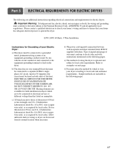
... NAMEPLATE. DO NOT CONNECT DRYER TO 110, 115, OR 120 VOLT CIRCUIT. Refer to the latest edition of your dryer according to local code requirements. Part 5 ELECTRICAL REQUIREMENTS FOR ELECTRIC DRYERS The following are included in the following pages. Heating elements are available for electric dryers. ! d) The power cord (pigtail) connection...
... NAMEPLATE. DO NOT CONNECT DRYER TO 110, 115, OR 120 VOLT CIRCUIT. Refer to the latest edition of your dryer according to local code requirements. Part 5 ELECTRICAL REQUIREMENTS FOR ELECTRIC DRYERS The following are included in the following pages. Heating elements are available for electric dryers. ! d) The power cord (pigtail) connection...
Owners Manual
Page 20
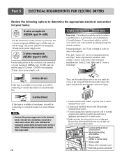
... wire (white) of the terminal block (hooked end facing to the right) and pinch the hook together and screw tightly. 1. Colored wire should be replaced. Part 5 ELECTRICAL REQUIREMENTS FOR ELECTRIC DRYERS Review the following options to determine the appropriate electrical connection for your home: 4-wire receptacle (NEMA type14-30R) Use the...
... wire (white) of the terminal block (hooked end facing to the right) and pinch the hook together and screw tightly. 1. Colored wire should be replaced. Part 5 ELECTRICAL REQUIREMENTS FOR ELECTRIC DRYERS Review the following options to determine the appropriate electrical connection for your home: 4-wire receptacle (NEMA type14-30R) Use the...
Owners Manual
Page 21
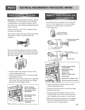
... not allow the use a 4-wire connection. Connect neutral wire (white) of a 3-wire connection, or you are on tight and power cord is in right position. 1. Part 5 ELECTRICAL REQUIREMENTS FOR ELECTRIC DRYERS 3-wire connection : Direct wire Important : Grounding through the neutral conductor is prohibited for dryer to be replaced.
... not allow the use a 4-wire connection. Connect neutral wire (white) of a 3-wire connection, or you are on tight and power cord is in right position. 1. Part 5 ELECTRICAL REQUIREMENTS FOR ELECTRIC DRYERS 3-wire connection : Direct wire Important : Grounding through the neutral conductor is prohibited for dryer to be replaced.
Owners Manual
Page 22
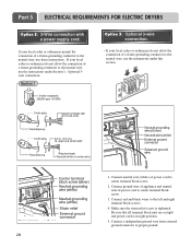
... ground wire of appliance and neutral wire of power cord to center terminal block screw. 3. Make sure the strain relief screw is in right position. 5. Part 5 ELECTRICAL REQUIREMENTS FOR ELECTRIC DRYERS Option 2: 3-Wire connection with a power supply cord. Connect a independent ground wire from external ground connector to the left and right...
... ground wire of appliance and neutral wire of power cord to center terminal block screw. 3. Make sure the strain relief screw is in right position. 5. Part 5 ELECTRICAL REQUIREMENTS FOR ELECTRIC DRYERS Option 2: 3-Wire connection with a power supply cord. Connect a independent ground wire from external ground connector to the left and right...


