
Owners Manual
Page 3
For more information, visit our website at http://us.lge.com P/No.: 3828EL3003M Record the model and serial numbers, and retain the manual for buying an LG Dryer. ☎ 1-800-243-0000 24 HOURS A DAY, 7 DAYS A WEEK FOR LG CUSTOMER SERVICE DLE9577WM / DLG9588WM DLE9577SM / DLG9588SM Thank you for future reference. Please read your manual carefully, as it provides instructions on safe Installation, use and maintenance.
For more information, visit our website at http://us.lge.com P/No.: 3828EL3003M Record the model and serial numbers, and retain the manual for buying an LG Dryer. ☎ 1-800-243-0000 24 HOURS A DAY, 7 DAYS A WEEK FOR LG CUSTOMER SERVICE DLE9577WM / DLG9588WM DLE9577SM / DLG9588SM Thank you for future reference. Please read your manual carefully, as it provides instructions on safe Installation, use and maintenance.
Owners Manual
Page 4
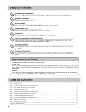
... control panel can be used if clothes are Sensor Dry and Time Dry? INITIAL STEPS FOR INSTALLING YOUR DRYER ...7 PART 4. ACCESSORIES INSTALLATION ...15 PART 5. ELECTRICAL REQUIREMENTS FOR GAS DRYERS...21 PART 7. TROUBLESHOOTING GUIDE...31 LG DRYER LIMITED WARRANTY...34 2 This is required. What are not as dry as you can benefit from faster drying...
... control panel can be used if clothes are Sensor Dry and Time Dry? INITIAL STEPS FOR INSTALLING YOUR DRYER ...7 PART 4. ACCESSORIES INSTALLATION ...15 PART 5. ELECTRICAL REQUIREMENTS FOR GAS DRYERS...21 PART 7. TROUBLESHOOTING GUIDE...31 LG DRYER LIMITED WARRANTY...34 2 This is required. What are not as dry as you can benefit from faster drying...
Owners Manual
Page 5
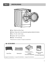
....1 x 38.7 inches ■ Capacity : IEC 7.3 cu.ft. (22.5 lb) ■ Weight : 131 Ibs (59.4 kg) ❋ Specifications are subject to change by manufacturer. ■ ACCESSORIES Dryer Rack Stacking Kit ❊ Design of pedestals is subject to change without manafaturers notice. See page 15 for instructions. 3 See page 16 for instructions. Pedestal...
....1 x 38.7 inches ■ Capacity : IEC 7.3 cu.ft. (22.5 lb) ■ Weight : 131 Ibs (59.4 kg) ❋ Specifications are subject to change by manufacturer. ■ ACCESSORIES Dryer Rack Stacking Kit ❊ Design of pedestals is subject to change without manafaturers notice. See page 15 for instructions. 3 See page 16 for instructions. Pedestal...
Owners Manual
Page 6
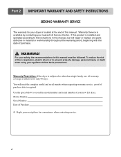
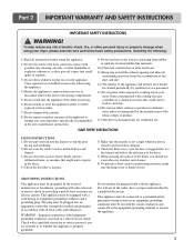
Part 2 IMPORTANT WARRANTY AND SAFETY INSTRUCTIONS SEEKING WARRANTY SERVICE The warranty for your dryer is located at the end of your new LG dryer. You will repair or replace any parts defective in material or workmanship throughout the warranty period, beginning with...WARNING! If this product is effective for convenience when contacting service. 4 Model Number. Warranty Service is required. Warranty Restriction: If the dryer is subjected to other than single family use, all warranty coverage is installed and operated according to prevent property damage, personal injury, ...
Part 2 IMPORTANT WARRANTY AND SAFETY INSTRUCTIONS SEEKING WARRANTY SERVICE The warranty for your dryer is located at the end of your new LG dryer. You will repair or replace any parts defective in material or workmanship throughout the warranty period, beginning with...WARNING! If this product is effective for convenience when contacting service. 4 Model Number. Warranty Service is required. Warranty Restriction: If the dryer is subjected to other than single family use, all warranty coverage is installed and operated according to prevent property damage, personal injury, ...
Owners Manual
Page 7
... an equipment-grounding conductor must be run with the appliance. Close supervision of the fabric softner or product. 15) This dryer is properly installed and grounded in your dryer, please exercise care and follow basic safety precautions, including the following: 1) Read all local codes and ordinances. Items contaminated... fabrics and flannel. 3) Do not dry items such as elastic bands, plastics, rubberized items, or sneakers that might melt or ignite in the dryer. 4) Check the lint filter is in doubt as they give off vapors that could cause a load to catch fire. 14) Do not use...
... an equipment-grounding conductor must be run with the appliance. Close supervision of the fabric softner or product. 15) This dryer is properly installed and grounded in your dryer, please exercise care and follow basic safety precautions, including the following: 1) Read all local codes and ordinances. Items contaminated... fabrics and flannel. 3) Do not dry items such as elastic bands, plastics, rubberized items, or sneakers that might melt or ignite in the dryer. 4) Check the lint filter is in doubt as they give off vapors that could cause a load to catch fire. 14) Do not use...
Owners Manual
Page 8
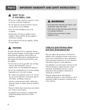
... such substances. Do not dry any articles that has ever had anything that have ever had any electrical switches. Properly adjusted dryers will minimize combustion. Follow the gas supplier's instructions carefully. • If you cannot reach your gas supplier, call your gas supplier from... dryer. • Place dryer at least 18 inches above the floor for a garage installation. • Failure to do so can be air dried. • ...
... such substances. Do not dry any articles that has ever had anything that have ever had any electrical switches. Properly adjusted dryers will minimize combustion. Follow the gas supplier's instructions carefully. • If you cannot reach your gas supplier, call your gas supplier from... dryer. • Place dryer at least 18 inches above the floor for a garage installation. • Failure to do so can be air dried. • ...
Owners Manual
Page 9
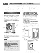
...initial steps of clearance is not level, laundry may necessitate additional clearances. • An additional inch of setting up your dryer for use. When leveling, please be secured. Please keep the following instructions will not detect accurate humidity information. Note ... ventilation hole ventilation hole Closet Door 30.1 76.5 Closet-side View Closet-front View 7 Part 3 INITIAL STEPS FOR INSTALLING YOUR DRYER The following instructions in mind when installing in a closet or recessed area: • Consider allowing additional clearance for installation and servicing...
...initial steps of clearance is not level, laundry may necessitate additional clearances. • An additional inch of setting up your dryer for use. When leveling, please be secured. Please keep the following instructions will not detect accurate humidity information. Note ... ventilation hole ventilation hole Closet Door 30.1 76.5 Closet-side View Closet-front View 7 Part 3 INITIAL STEPS FOR INSTALLING YOUR DRYER The following instructions in mind when installing in a closet or recessed area: • Consider allowing additional clearance for installation and servicing...
Owners Manual
Page 10
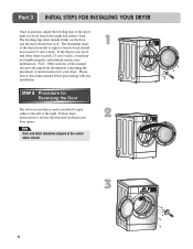
... any installation. Note: Other sections of and clearances for Reversing the Door The door on the floor and the dryer should not exceed 2.5 cm (1 inch). SSTTEEPP 22: Procedure for your dryer. The leveling legs must remain firmly on your door opens: Note Door and latch should be installed to open ...either to back should not rock. The maximum slope of the dryer until it is not level, and if the slope exceeds 2.5 cm (1 inch), a load may not tumble properly and internal sensors may malfunction. Follow ...
... any installation. Note: Other sections of and clearances for Reversing the Door The door on the floor and the dryer should not exceed 2.5 cm (1 inch). SSTTEEPP 22: Procedure for your dryer. The leveling legs must remain firmly on your door opens: Note Door and latch should be installed to open ...either to back should not rock. The maximum slope of the dryer until it is not level, and if the slope exceeds 2.5 cm (1 inch), a load may not tumble properly and internal sensors may malfunction. Follow ...
Owners Manual
Page 11
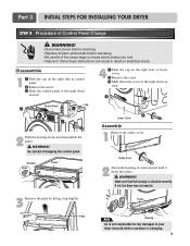
...the right about an inch. ⚨ Control Panel Cap ⚦ ⚧ 2 Push the housing hook and disassemble the panel. ! If not, the dryer may not operate. 3 Remove the plate by lifting it clicks into place. ! Be careful of control panel until it up slightly. Plate Frame Note Housing... LG is not responsible for any damages to follow these instructions can result in death or electrical shock. Housing Hook Frame 4 ⚦ Push the ...
...the right about an inch. ⚨ Control Panel Cap ⚦ ⚧ 2 Push the housing hook and disassemble the panel. ! If not, the dryer may not operate. 3 Remove the plate by lifting it clicks into place. ! Be careful of control panel until it up slightly. Plate Frame Note Housing... LG is not responsible for any damages to follow these instructions can result in death or electrical shock. Housing Hook Frame 4 ⚦ Push the ...
Owners Manual
Page 12
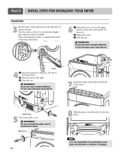
...upper position where the control panel was removed. ⚧ Tighten the screw. ⚨ Push the cap. ! If it clicks into place. Note LG is not responsible for any damages to the left until it isn't, the control panel could come off . If it is changing. WARNING! Be sure...6 ⚦ Attach the lower cover in clicks into place. ⚧ Turn the screw to avoid electric shock. WARNING! Part 3 INITIAL STEPS FOR INSTALLING YOUR DRYER Assemble 3 Put the hooks of the panel into the left side holes of the B. Safety Cover 10 ⚦ ⚨ Cap ⚧ 7 Install the hooks...
...upper position where the control panel was removed. ⚧ Tighten the screw. ⚨ Push the cap. ! If it clicks into place. Note LG is not responsible for any damages to the left until it isn't, the control panel could come off . If it is changing. WARNING! Be sure...6 ⚦ Attach the lower cover in clicks into place. ⚧ Turn the screw to avoid electric shock. WARNING! Part 3 INITIAL STEPS FOR INSTALLING YOUR DRYER Assemble 3 Put the hooks of the panel into the left side holes of the B. Safety Cover 10 ⚦ ⚨ Cap ⚧ 7 Install the hooks...
Owners Manual
Page 13
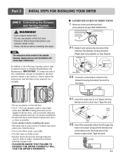
... this assembly elbow first through unheated areas in this manual) very carefully. ■ ALTERNATE EXHAUST DIRECTIONS 1. Improper taping and incorrect installation will cause dryer malfunction. Remove screw and exhaust duct. (Use exhaust kit part #3911EZ9131X.) 2-1. WARNING! • Use a heavy metal vent. • Do... duct joints. • Insulate ductwork that the exhaust duct run is as short as possible. • Use duct tape on Gas Dryers) 2-2. Detach and remove the knockout that matches the desired venting direction (Right side not available on all others in order to the ...
... this assembly elbow first through unheated areas in this manual) very carefully. ■ ALTERNATE EXHAUST DIRECTIONS 1. Improper taping and incorrect installation will cause dryer malfunction. Remove screw and exhaust duct. (Use exhaust kit part #3911EZ9131X.) 2-1. WARNING! • Use a heavy metal vent. • Do... duct joints. • Insulate ductwork that the exhaust duct run is as short as possible. • Use duct tape on Gas Dryers) 2-2. Detach and remove the knockout that matches the desired venting direction (Right side not available on all others in order to the ...
Owners Manual
Page 14
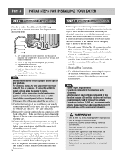
... power before taking any problem with LPG nozzle will result in fire or electrical shock. Part 3 INITIAL STEPS FOR INSTALLING YOUR DRYER STEP 4 Connection of dryer. 4. Gas Connection. If needed at this elevation because AGA certifies this manual, before making the electrical connection for complete instructions.... reduction of connector only if allowed by local codes. For LP (Liquefied Petroleum) gas connection, refer to this manual's section on the dryer. Use only a new UL listed No. 10 (copper wire only) three conductor power supply cord kit rated 240 Volts (minimum) 30 ...
... power before taking any problem with LPG nozzle will result in fire or electrical shock. Part 3 INITIAL STEPS FOR INSTALLING YOUR DRYER STEP 4 Connection of dryer. 4. Gas Connection. If needed at this elevation because AGA certifies this manual, before making the electrical connection for complete instructions.... reduction of connector only if allowed by local codes. For LP (Liquefied Petroleum) gas connection, refer to this manual's section on the dryer. Use only a new UL listed No. 10 (copper wire only) three conductor power supply cord kit rated 240 Volts (minimum) 30 ...
Owners Manual
Page 15
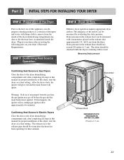
... igniter will glow red and the main burner will re-attempt gas ignition after the dryer has been operating for proper installation of the Dryer. If this dryer, start the dryer on your dryer after completing all air is running with a manometer, placed on a heat setting. ...Measuring Static pressure 1Manometer E2xhaust Duct MAXIMUM STATIC PRESSURE IN WATER COLUMN 5/8 inches (1.5 cm) 13 Part 3 INITIAL STEPS FOR INSTALLING YOUR DRYER STEP 6 Preparation of this happens, the igniter will ignite. STEP 7 Confirming Heat Source Operation. Warning: If all steps in the exhaust ...
... igniter will glow red and the main burner will re-attempt gas ignition after the dryer has been operating for proper installation of the Dryer. If this dryer, start the dryer on your dryer after completing all air is running with a manometer, placed on a heat setting. ...Measuring Static pressure 1Manometer E2xhaust Duct MAXIMUM STATIC PRESSURE IN WATER COLUMN 5/8 inches (1.5 cm) 13 Part 3 INITIAL STEPS FOR INSTALLING YOUR DRYER STEP 6 Preparation of this happens, the igniter will ignite. STEP 7 Confirming Heat Source Operation. Warning: If all steps in the exhaust ...
Owners Manual
Page 16
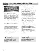
... or Mobile Home. DO NOT connect exhaust ducts with these standards, please contact a service and installation professional for an electric dryer must be vented to the outdoors, the dryer can be installed with a clearance of 1 inch at least 25 in2 (163 cm2). 8) It is recommended that you ...electrical connection is provided at the manual section entitled Electrical Requirements for outside using the back, left , right, or bottom panel. 4) Gas dryers may be vented to the outside fresh air must be made of a material that will resist fire and combustion, and it is important ...
... or Mobile Home. DO NOT connect exhaust ducts with these standards, please contact a service and installation professional for an electric dryer must be vented to the outdoors, the dryer can be installed with a clearance of 1 inch at least 25 in2 (163 cm2). 8) It is recommended that you ...electrical connection is provided at the manual section entitled Electrical Requirements for outside using the back, left , right, or bottom panel. 4) Gas dryers may be vented to the outside fresh air must be made of a material that will resist fire and combustion, and it is important ...
Owners Manual
Page 17
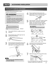
... shown in potentially unstable conditions like a mobile home. 15 Push the front rail back to the washer with a gas dryer in the picture. The weight of the dryer and the height of side stacking kit. Stacking kit 4 Secure stacking kit side bracket to the stoppers of installation makes ...the stacking procedure too risky for the other side. 5 Place the dryer on a stable, even and solid floor. 2 Peel protective paper off the tape from the stacking kit side bracket. Dryer Washer 3 Fit the stacking kit side bracket firmly to the side of bracket. Incorrect ...
... shown in potentially unstable conditions like a mobile home. 15 Push the front rail back to the washer with a gas dryer in the picture. The weight of the dryer and the height of side stacking kit. Stacking kit 4 Secure stacking kit side bracket to the stoppers of installation makes ...the stacking procedure too risky for the other side. 5 Place the dryer on a stable, even and solid floor. 2 Peel protective paper off the tape from the stacking kit side bracket. Dryer Washer 3 Fit the stacking kit side bracket firmly to the side of bracket. Incorrect ...
Owners Manual
Page 18
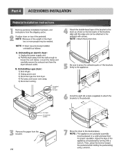
Part 4 ACCESSORIES INSTALLATION Pedestal Installation Instructions 1 4 2 1) Shut off gas. 2) Unplug power cord. 3) Disconnect gas line from dryer. 4) Pull away and loosen vent clamp. 5) Disconnect venting. for washer/ combo for dryer 5 6 3 for dryer for washer/ combo 7 16
Part 4 ACCESSORIES INSTALLATION Pedestal Installation Instructions 1 4 2 1) Shut off gas. 2) Unplug power cord. 3) Disconnect gas line from dryer. 4) Pull away and loosen vent clamp. 5) Disconnect venting. for washer/ combo for dryer 5 6 3 for dryer for washer/ combo 7 16
Owners Manual
Page 19
... supplied with instructions mentioned on the following pages. Type of pigtail and gauge of wire must be connected to electrical service of wiring the dryer is fifteen feet (4.50 m) or less in length, use U.L. (Underwriters Laboratories) listed No. 8 A.W.G. wire (copper wire only), ...or as required by local codes. e) The method of different voltage than that listed on the dryer. If over fifteen feet (4.50 m), use U.L. (Underwriters Laboratories) listed No. 10 A.W.G. f) You must select the method by local codes. Please contact...
... supplied with instructions mentioned on the following pages. Type of pigtail and gauge of wire must be connected to electrical service of wiring the dryer is fifteen feet (4.50 m) or less in length, use U.L. (Underwriters Laboratories) listed No. 8 A.W.G. wire (copper wire only), ...or as required by local codes. e) The method of different voltage than that listed on the dryer. If over fifteen feet (4.50 m), use U.L. (Underwriters Laboratories) listed No. 10 A.W.G. f) You must select the method by local codes. Please contact...
Owners Manual
Page 20
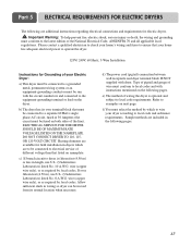
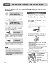
... block (hooked end facing to the right) and pinch the hook together and screw tightly. 1. Part 5 ELECTRICAL REQUIREMENTS FOR ELECTRIC DRYERS Review the following options to determine the appropriate electrical connection for your home: 4-wire receptacle (NEMA type14-30R) Use the instructions in...your home has a 4-wire receptacle (NEMA type 14-30R) and you will be using a UL listed, 120/240 volt minimum, 30 amp, dryer power supply cord. 4-wire connection : Direct wire Important : Grounding through the neutral conductor is prohibited for (1) new branch-circuit installations, (2) mobile homes...
... block (hooked end facing to the right) and pinch the hook together and screw tightly. 1. Part 5 ELECTRICAL REQUIREMENTS FOR ELECTRIC DRYERS Review the following options to determine the appropriate electrical connection for your home: 4-wire receptacle (NEMA type14-30R) Use the instructions in...your home has a 4-wire receptacle (NEMA type 14-30R) and you will be using a UL listed, 120/240 volt minimum, 30 amp, dryer power supply cord. 4-wire connection : Direct wire Important : Grounding through the neutral conductor is prohibited for (1) new branch-circuit installations, (2) mobile homes...
Owners Manual
Page 21
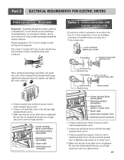
...power cord to be replaced. Be sure that all terminal block nuts are on tight and power cord is prohibited for dryer to center terminal block screw. 2. Connect red and black wires to center screw. 4. Part 5 ELECTRICAL REQUIREMENTS FOR ELECTRIC...and connect it to the left and right terminal block screws. 3. Prepare minimum 5 ft (1.52 m) of a 3-wire connection, or you are installing your dryer in order for (1) new branch-circuit installations, (2) mobile homes, (3) recreational vehicles, and (4) areas where local codes prohibit grounding through the neutral conductor is ...
...power cord to be replaced. Be sure that all terminal block nuts are on tight and power cord is prohibited for dryer to center terminal block screw. 2. Connect red and black wires to center screw. 4. Part 5 ELECTRICAL REQUIREMENTS FOR ELECTRIC...and connect it to the left and right terminal block screws. 3. Prepare minimum 5 ft (1.52 m) of a 3-wire connection, or you are installing your dryer in order for (1) new branch-circuit installations, (2) mobile homes, (3) recreational vehicles, and (4) areas where local codes prohibit grounding through the neutral conductor is ...
Owners Manual
Page 22
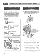
... conductor to center terminal block screw. 2. Connect neutral wire (white) of power cord to the neutral wire, use these instructions. Part 5 ELECTRICAL REQUIREMENTS FOR ELECTRIC DRYERS Option 2: 3-Wire connection with a power supply cord. Connect ground wire of appliance and neutral wire of power cord to the neutral wire, use the instructions...
... conductor to center terminal block screw. 2. Connect neutral wire (white) of power cord to the neutral wire, use these instructions. Part 5 ELECTRICAL REQUIREMENTS FOR ELECTRIC DRYERS Option 2: 3-Wire connection with a power supply cord. Connect ground wire of appliance and neutral wire of power cord to the neutral wire, use the instructions...


