

Service Manual
Page 4
CONTENTS 1. DRYER CYCLE PROCESS ...13 5. TEST 7 GAS VALVE TEST - DISASSEMBLY INSTRUCTIONS 32 12. DRUM & MOTOR ASSEMBLY: ELECTRIC MODEL 41 12-3-2. FEATURES AND BENEFITS ...6 3. MOTOR DIAGRAM AND SCHEMATIC 17 7. TEST 3 MOTOR TEST 24 9-4. TEST 6 HEATER SWITCH TEST - ELECTRIC MODEL 27 9-7. REPLACEMENT PARTS LIST 43 3 WIRING DIAGRAM ...19 9. TEST 4 MOISTURE SENSOR 25 9-5. EXPLODED VIEW ...39...
CONTENTS 1. DRYER CYCLE PROCESS ...13 5. TEST 7 GAS VALVE TEST - DISASSEMBLY INSTRUCTIONS 32 12. DRUM & MOTOR ASSEMBLY: ELECTRIC MODEL 41 12-3-2. FEATURES AND BENEFITS ...6 3. MOTOR DIAGRAM AND SCHEMATIC 17 7. TEST 3 MOTOR TEST 24 9-4. TEST 6 HEATER SWITCH TEST - ELECTRIC MODEL 27 9-7. REPLACEMENT PARTS LIST 43 3 WIRING DIAGRAM ...19 9. TEST 4 MOISTURE SENSOR 25 9-5. EXPLODED VIEW ...39...
Service Manual
Page 9
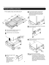
...a wrench. Adjust the legs of side brackets. Pedestal Installation Instructions For washer, dryer, and combo LG 27" 4 AAtftaecr hretmheovdinogubthle-pfarocteedcttivaepecoovfetrhinegbfroamcktehteto the dardyheersaivsesshuorfwacnes, oaltighne tbhenstcpreawrtshoolfetshien bthreackets ablriagcnkwetisthwtihthetheedgmeaatcnhdincgahnoblees aintttahcehpeeddteostahle pbeadseesatnadl ... Remove the paper from the shipping carton. 2 Position the dryer on a solid and level floor for dryer 5 Be sure to press the adhesive parts of the brackets firmly to the appliance. 6 Install the ...
...a wrench. Adjust the legs of side brackets. Pedestal Installation Instructions For washer, dryer, and combo LG 27" 4 AAtftaecr hretmheovdinogubthle-pfarocteedcttivaepecoovfetrhinegbfroamcktehteto the dardyheersaivsesshuorfwacnes, oaltighne tbhenstcpreawrtshoolfetshien bthreackets ablriagcnkwetisthwtihthetheedgmeaatcnhdincgahnoblees aintttahcehpeeddteostahle pbeadseesatnadl ... Remove the paper from the shipping carton. 2 Position the dryer on a solid and level floor for dryer 5 Be sure to press the adhesive parts of the brackets firmly to the appliance. 6 Install the ...

Service Manual
Page 38
..., left or right side as desired. (Right Side Vent not available on Gas dryer the order of work. Wrap duct tape around joint. Failure to the base. (Duct is a SVC part) DUCT TAPE 3-1. Remove a screw and the exhaust duct. 2-1. DRYER EXHAUST CHANGE ! WARNING ! Insert the elbow duct assembly through the side opening and...
..., left or right side as desired. (Right Side Vent not available on Gas dryer the order of work. Wrap duct tape around joint. Failure to the base. (Duct is a SVC part) DUCT TAPE 3-1. Remove a screw and the exhaust duct. 2-1. DRYER EXHAUST CHANGE ! WARNING ! Insert the elbow duct assembly through the side opening and...


