
Service Manual
Page 1
MODEL : DLE8377WM/DLG8388WM DLE8377NM/DLG8388NM DLE7177WM/DLG7188WM U.S.A. Website: http://us.lgservice.com Canadian Website: http://lg.ca ELECTRIC & GAS DRYER SERVICE MANUAL CAUTION READ THIS MANUAL CAREFULLY IN ORDER TO PROPERLY DIAGNOSE PROBLEMS AND TO SAFELY PROVIDE QUALITY SERVICE ON THESE DRYERS.
MODEL : DLE8377WM/DLG8388WM DLE8377NM/DLG8388NM DLE7177WM/DLG7188WM U.S.A. Website: http://us.lgservice.com Canadian Website: http://lg.ca ELECTRIC & GAS DRYER SERVICE MANUAL CAUTION READ THIS MANUAL CAREFULLY IN ORDER TO PROPERLY DIAGNOSE PROBLEMS AND TO SAFELY PROVIDE QUALITY SERVICE ON THESE DRYERS.

Service Manual
Page 4
DRYER CYCLE PROCESS ...13 5. MOTOR DIAGRAM AND SCHEMATIC 17 7. TEST 2 THERMISTOR TEST 22 9-3. GAS MODEL 28 9-8 TEST 8 SEMI-CONDUCTOR 29 10. EXPLODED VIEW ...39 12-1. CONTROL PANEL & PLATE ASSEMBLY 39 12-2. SPECIFICATIONS ...4 2. DIAGNOSTIC TEST ...20 9-1. TEST 4 MOISTURE SENSOR 25 9-5. TEST 7 GAS VALVE TEST - TEST 1 120V AC ELECTRICAL... SUPPLY 21 9-2. REPLACEMENT PARTS LIST 43 3 COMPONENT TESTING INFORMATION 14 6. TEST 6 HEATER SWITCH TEST - ELECTRIC MODEL 27 9-7. TEST 3 MOTOR TEST 24 9-4. CABINET ...
DRYER CYCLE PROCESS ...13 5. MOTOR DIAGRAM AND SCHEMATIC 17 7. TEST 2 THERMISTOR TEST 22 9-3. GAS MODEL 28 9-8 TEST 8 SEMI-CONDUCTOR 29 10. EXPLODED VIEW ...39 12-1. CONTROL PANEL & PLATE ASSEMBLY 39 12-2. SPECIFICATIONS ...4 2. DIAGNOSTIC TEST ...20 9-1. TEST 4 MOISTURE SENSOR 25 9-5. TEST 7 GAS VALVE TEST - TEST 1 120V AC ELECTRICAL... SUPPLY 21 9-2. REPLACEMENT PARTS LIST 43 3 COMPONENT TESTING INFORMATION 14 6. TEST 6 HEATER SWITCH TEST - ELECTRIC MODEL 27 9-7. TEST 3 MOTOR TEST 24 9-4. CABINET ...
Service Manual
Page 5
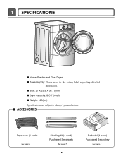
I Weight: 126(Ibs) Specifications are subject to the rating label regarding detailed information. I ACCESSORIES Dryer rack (1 each) See page 6 Stacking kit (1 each) Purchased Separately See page 7 4 Pedestal (1 each) Purchased Separately See page 8 1 SPECIFICATIONS I Name: Electric and Gas Dryer I Dryer capacity: IEC 7.3 cu.ft. I Size: 27 X 29.9 X 38.7 (inch) I Power supply: Please refer to change by manufacturer.
I Weight: 126(Ibs) Specifications are subject to the rating label regarding detailed information. I ACCESSORIES Dryer rack (1 each) See page 6 Stacking kit (1 each) Purchased Separately See page 7 4 Pedestal (1 each) Purchased Separately See page 8 1 SPECIFICATIONS I Name: Electric and Gas Dryer I Dryer capacity: IEC 7.3 cu.ft. I Size: 27 X 29.9 X 38.7 (inch) I Power supply: Please refer to change by manufacturer.
Service Manual
Page 6
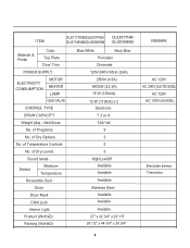
...ITEM DLE7177WM/DLE8377WM DLE8377NM DLG7188WM/DLG8388WM DLG8388NM Material & Finish Color Top Plate Door Trim POWER SUPPLY ELECTRICITY CONSUMPTION MOTOR HEATER LAMP GAS VALVE CONTROL TYPE DRUM CAPACITY Weight (lbs) - Net/Gross No. of Dry Levels Sound levels Sensor Moisture Temperature Reversible Door Drum Dryer Rack...Off Available Available Available Stainless Steel Available Avaiable Avaiable 27" x 42 3/4" x 28 1/3" 29 1/2" x 44 3/4" x 30 3/4" REMARK AC 120V AC 240V (ELECTRIC MODEL) AC 120V AC 120V (GAS MODEL) Electrode sensor Thermistor 5 of Temperature Controls No.
...ITEM DLE7177WM/DLE8377WM DLE8377NM DLG7188WM/DLG8388WM DLG8388NM Material & Finish Color Top Plate Door Trim POWER SUPPLY ELECTRICITY CONSUMPTION MOTOR HEATER LAMP GAS VALVE CONTROL TYPE DRUM CAPACITY Weight (lbs) - Net/Gross No. of Dry Levels Sound levels Sensor Moisture Temperature Reversible Door Drum Dryer Rack...Off Available Available Available Stainless Steel Available Avaiable Avaiable 27" x 42 3/4" x 28 1/3" 29 1/2" x 44 3/4" x 30 3/4" REMARK AC 120V AC 240V (ELECTRIC MODEL) AC 120V AC 120V (GAS MODEL) Electrode sensor Thermistor 5 of Temperature Controls No.
Service Manual
Page 10
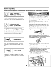
Electric Dryer Only Review the following options to determine the appropriate electrical connection for (1) new branch-circuit installations, (2) mobile homes, and (3) recreational vehicles, and (4) areas where local codes prohibit grounding through the neutral conductor is...) of appliance and connect it to center screw. 4. Make sure that all terminal block nuts are on tight and power cord is in order for dryer to be connecting to external ground screw and move neutral ground wire of length in right position. 1" (2.5 cm) D 3V2" E (8.9 cm) F a C b 9 After cutting 11...
Electric Dryer Only Review the following options to determine the appropriate electrical connection for (1) new branch-circuit installations, (2) mobile homes, and (3) recreational vehicles, and (4) areas where local codes prohibit grounding through the neutral conductor is...) of appliance and connect it to center screw. 4. Make sure that all terminal block nuts are on tight and power cord is in order for dryer to be connecting to external ground screw and move neutral ground wire of length in right position. 1" (2.5 cm) D 3V2" E (8.9 cm) F a C b 9 After cutting 11...
Service Manual
Page 20
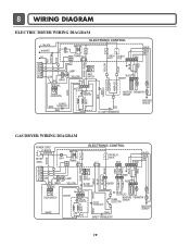
LIMIT THERMOSTAT MOISTURE SENSOR GAS DRYER WIRING DIAGRAM POWER CORD ELECTRONIC CONTROL L1 BLACK N WHITE GN/YL 1 WH1 TRANS 12 BL2 TAP RELAY BLACK YL2 BL3 BLACK WHITE RED NA6 RED ... THERMOSTAT WHITE DC VALVE1 DC VALVE2 MOISTURE THERMISTOR FLAME SENSOR DETECTOR MOISTURE SENSOR CENTRIFUGAL SWITCH RED WHITE NC NO GRAY SAFETY THERMOSTAT 19 8 WIRING DIAGRAM ELECTRIC DRYER WIRING DIAGRAM PLC MODEM RED WHITE B;ACK ELECTRONIC CONTROL L1 BLACK N WHITE L2 1 WH1 1 2 TRANS BL2 34 3 1 TAP RELAY TAP RELAY BLACK WHITE NA6 6 5 432...
LIMIT THERMOSTAT MOISTURE SENSOR GAS DRYER WIRING DIAGRAM POWER CORD ELECTRONIC CONTROL L1 BLACK N WHITE GN/YL 1 WH1 TRANS 12 BL2 TAP RELAY BLACK YL2 BL3 BLACK WHITE RED NA6 RED ... THERMOSTAT WHITE DC VALVE1 DC VALVE2 MOISTURE THERMISTOR FLAME SENSOR DETECTOR MOISTURE SENSOR CENTRIFUGAL SWITCH RED WHITE NC NO GRAY SAFETY THERMOSTAT 19 8 WIRING DIAGRAM ELECTRIC DRYER WIRING DIAGRAM PLC MODEM RED WHITE B;ACK ELECTRONIC CONTROL L1 BLACK N WHITE L2 1 WH1 1 2 TRANS BL2 34 3 1 TAP RELAY TAP RELAY BLACK WHITE NA6 6 5 432...
Service Manual
Page 22
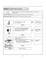
...(White Wire) Is 110~125V? YES Check if the voltage measured between Connector BK2 or WH2- (Black Wire) Linked to and avoid an electric shock. BK2 or WH2 WH1 BK WH 12 1 Check the outlet, is disconnected. NO - Check if Terminal Block and Power Cord are ...connected (Check Plug ). Trouble Symptom No power was applied to Controller. Connector linked to Controller. (LED,LCD Display off) Measurement Condition With Dryer Power On; NO • Check the fuse or circuit breaker. • Check if Power NO Cord is properly connected. Does Power Cord N ...
...(White Wire) Is 110~125V? YES Check if the voltage measured between Connector BK2 or WH2- (Black Wire) Linked to and avoid an electric shock. BK2 or WH2 WH1 BK WH 12 1 Check the outlet, is disconnected. NO - Check if Terminal Block and Power Cord are ...connected (Check Plug ). Trouble Symptom No power was applied to Controller. Connector linked to Controller. (LED,LCD Display off) Measurement Condition With Dryer Power On; NO • Check the fuse or circuit breaker. • Check if Power NO Cord is properly connected. Does Power Cord N ...
Service Manual
Page 23
... on Burner Temperature Control below 52 4°C. White Tab Relay) 22 Trouble Symptom Check the Tab Relays Connection properly. Connector linked to and avoid an electric shock. Black Tab Relay) Tap relay 1 Tap relay 2 Check the Matching color Between Harness wire and Tab Relay. (White Housing - Turn on Heater1. Low Extra... Heater (Elec) Tab Relay 1 Tab Relay 2 High Mid High Medium Tab Relay 1 Tab Relay 2 Heater 1 Heater 2 Remark on on on on Burner 2. Measurement Condition With Dryer Power On; Turn on Temperature Control below 70 4°C.
... on Burner Temperature Control below 52 4°C. White Tab Relay) 22 Trouble Symptom Check the Tab Relays Connection properly. Connector linked to and avoid an electric shock. Black Tab Relay) Tap relay 1 Tap relay 2 Check the Matching color Between Harness wire and Tab Relay. (White Housing - Turn on Heater1. Low Extra... Heater (Elec) Tab Relay 1 Tab Relay 2 High Mid High Medium Tab Relay 1 Tab Relay 2 Heater 1 Heater 2 Remark on on on on Burner 2. Measurement Condition With Dryer Power On; Turn on Temperature Control below 70 4°C.

Service Manual
Page 27
...4.0V ) Remark Weight after removing from the Controller. Is the measurement within the range of Table 2 NO when measuring the voltage in Electric load, is resistance below 1Ω? Take 6pin Connector from Washing Machine Damp Dry 10% ~ Dried clothes 205 ~ 240 Over 4.0V ...Completely-dried clothes 26 Normal Condition Table 2. Measurement Condition Turn the Dryer's Power Off, then measure resistance. YES • Check Electro Load and Harness Connector. • Check Harnesslinking connector. • Replace ...
...4.0V ) Remark Weight after removing from the Controller. Is the measurement within the range of Table 2 NO when measuring the voltage in Electric load, is resistance below 1Ω? Take 6pin Connector from Washing Machine Damp Dry 10% ~ Dried clothes 205 ~ 240 Over 4.0V ...Completely-dried clothes 26 Normal Condition Table 2. Measurement Condition Turn the Dryer's Power Off, then measure resistance. YES • Check Electro Load and Harness Connector. • Check Harnesslinking connector. • Replace ...

Service Manual
Page 30
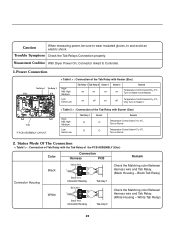
...• Check Igniter & Frame detect When measuring Valve 2 voltage, Value is more than DC 90V? Test 7 GAS Valve test - Measurement Condition With dryer power on Valve 1 Igniter Valve 2 Power On & Start (Normal Cycle) NO When measuring Valve 1 voltage, More than DC 90V? (10 sec ...8486;? Trouble Symptom While operating, Heating will not work. Gas Type Caution When measuring power, be sure to wear insulated gloves, to avoid electric shock. YES (Measure after Igniter off) YES NO • Check Gas connection or Gas supply When measuring terminal resistance on Valve 1 ...
...• Check Igniter & Frame detect When measuring Valve 2 voltage, Value is more than DC 90V? Test 7 GAS Valve test - Measurement Condition With dryer power on Valve 1 Igniter Valve 2 Power On & Start (Normal Cycle) NO When measuring Valve 1 voltage, More than DC 90V? (10 sec ...8486;? Trouble Symptom While operating, Heating will not work. Gas Type Caution When measuring power, be sure to wear insulated gloves, to avoid electric shock. YES (Measure after Igniter off) YES NO • Check Gas connection or Gas supply When measuring terminal resistance on Valve 1 ...


