
Service Manual
Page 4
... 13. ELECTRIC MODEL 28 9-7. GAS MODEL 29 10. SPECIFICATIONS ...4 2. INSTALLATION INSTRUCTIONS 6 4. COMPONENT TESTING INFORMATION 14 6. TEST 5 DOOR SWITCH TEST 27 9-6. TEST 7 GAS VALVE TEST - TEST 4 MOISTURE SENSOR 26 9-5. CHANGE GAS SETTING (NATURAL GAS, PROPANE GAS 30 11. REPLACEMENT PARTS LIST 43 3 DRYER CYCLE PROCESS ...13 5. TEST 3 MOTOR TEST 25 9-4. TEST 1 120V AC...
... 13. ELECTRIC MODEL 28 9-7. GAS MODEL 29 10. SPECIFICATIONS ...4 2. INSTALLATION INSTRUCTIONS 6 4. COMPONENT TESTING INFORMATION 14 6. TEST 5 DOOR SWITCH TEST 27 9-6. TEST 7 GAS VALVE TEST - TEST 4 MOISTURE SENSOR 26 9-5. CHANGE GAS SETTING (NATURAL GAS, PROPANE GAS 30 11. REPLACEMENT PARTS LIST 43 3 DRYER CYCLE PROCESS ...13 5. TEST 3 MOTOR TEST 25 9-4. TEST 1 120V AC...
Service Manual
Page 6
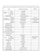
of Dry Levels Sound levels Sensor Moisture Temperature Reversible Door Drum Dryer Rack Child Lock Interior Light Product (WxHxD) Packing (WxHxD) DLE2516W / DLG2526W Blue White Porcelain Silver Spray 120V/240V 60Hz (26A) ... Steel Available Avaiable Avaiable 27" x 38.74" x 29.9" 29.5" x 44.1" x 31.3" 5 REMARK AC 120V AC 240V (ELECTRIC MODEL) AC 120V AC 120V (GAS MODEL) Electrode sensor Thermistor of Dry Options No. ITEM Material & Finish Color Top Plate Door Trim POWER SUPPLY ELECTRICITY CONSUMPTION MOTOR HEATER LAMP GAS VALVE CONTROL TYPE DRUM...
of Dry Levels Sound levels Sensor Moisture Temperature Reversible Door Drum Dryer Rack Child Lock Interior Light Product (WxHxD) Packing (WxHxD) DLE2516W / DLG2526W Blue White Porcelain Silver Spray 120V/240V 60Hz (26A) ... Steel Available Avaiable Avaiable 27" x 38.74" x 29.9" 29.5" x 44.1" x 31.3" 5 REMARK AC 120V AC 240V (ELECTRIC MODEL) AC 120V AC 120V (GAS MODEL) Electrode sensor Thermistor of Dry Options No. ITEM Material & Finish Color Top Plate Door Trim POWER SUPPLY ELECTRICITY CONSUMPTION MOTOR HEATER LAMP GAS VALVE CONTROL TYPE DRUM...
Service Manual
Page 20
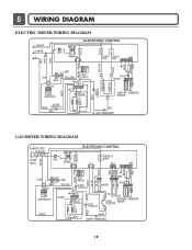
...OUTER COIL INNER COIL COM NO 1 2 GRAY NC 123 DOOR SWITCH WHITE LAMP YELLOW 1 2 3 BELT SWITCH 1 2 3 7 10 MOTOR OVERLOAD PROTECTOR BLUE HEATER 2 1 2 1 MOISTURE THERMISTOR SENSOR CENTRIFUGAL SWITCH BLOWER WHITE THERMOSTAT RED RED HI - LIMIT THERMOSTAT GAS DRYER WIRING DIAGRAM POWER CORD L1 BLACK N WHITE GN/YL WHITE 1 WH1 TRANS BL2... GRAY BLUE RED 23 1212 IGNITER BLUE 21 21 YELLOW MOTOR 2379 OVERLOAD PROTECTOR HI-LIMIT THERMOSTAT WHITE DC VALVE1 DC VALVE2 MOISTURE THERMISTOR FLAME SENSOR DETECTOR CENTRIFUGAL SWITCH RED WHITE NC NO GRAY SAFETY THERMOSTAT 19
...OUTER COIL INNER COIL COM NO 1 2 GRAY NC 123 DOOR SWITCH WHITE LAMP YELLOW 1 2 3 BELT SWITCH 1 2 3 7 10 MOTOR OVERLOAD PROTECTOR BLUE HEATER 2 1 2 1 MOISTURE THERMISTOR SENSOR CENTRIFUGAL SWITCH BLOWER WHITE THERMOSTAT RED RED HI - LIMIT THERMOSTAT GAS DRYER WIRING DIAGRAM POWER CORD L1 BLACK N WHITE GN/YL WHITE 1 WH1 TRANS BL2... GRAY BLUE RED 23 1212 IGNITER BLUE 21 21 YELLOW MOTOR 2379 OVERLOAD PROTECTOR HI-LIMIT THERMOSTAT WHITE DC VALVE1 DC VALVE2 MOISTURE THERMISTOR FLAME SENSOR DETECTOR CENTRIFUGAL SWITCH RED WHITE NC NO GRAY SAFETY THERMOSTAT 19
Service Manual
Page 21
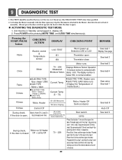
...If the door is open Thermistor close See test 1 Display: See page See test 2 Once Motor Motor runs 70 ~ 239 Measured Moisture Value. Do not use this DIAGNOSTIC TEST other than specified. 2. Pressing the START/PAUSE button CHECKING ACTION DISPLAY CHECKING POINT REMARK None ...pressing MORE TIME, and LESS TIME simultaneously. Proceed again with step 4 by pressing start 4 times) in the end. Displays Moisture Sensor Operation: If moisture sensor is contacted with the Door open may trip the Thermostat attached to the Heater, therefore do not activate it manually. (Do...
...If the door is open Thermistor close See test 1 Display: See page See test 2 Once Motor Motor runs 70 ~ 239 Measured Moisture Value. Do not use this DIAGNOSTIC TEST other than specified. 2. Pressing the START/PAUSE button CHECKING ACTION DISPLAY CHECKING POINT REMARK None ...pressing MORE TIME, and LESS TIME simultaneously. Proceed again with step 4 by pressing start 4 times) in the end. Displays Moisture Sensor Operation: If moisture sensor is contacted with the Door open may trip the Thermostat attached to the Heater, therefore do not activate it manually. (Do...
Service Manual
Page 27
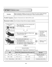
Test 4 Moisture sensor Caution Before measuring resistance, be sure to turn Power off, and do voltage discharge. (When discharging, contact the metal plug of Power cord with earth ... the 6 pin connector's Pin (Blue Wire) and Pin (Orange Wire) to Electro load: 1. Short with Dry Level. IMC Ratio and Display Value / Voltage (IMC: Initial Moisture Content) IMC 70% ~ 40% 40% ~ 20% Display Value Voltage (DC) (between 6 Pin terminal 50 ~ 130 2.5V 130 ~ 20 2.0V ~ 4.0V ) Remark Weight after removing from...
Test 4 Moisture sensor Caution Before measuring resistance, be sure to turn Power off, and do voltage discharge. (When discharging, contact the metal plug of Power cord with earth ... the 6 pin connector's Pin (Blue Wire) and Pin (Orange Wire) to Electro load: 1. Short with Dry Level. IMC Ratio and Display Value / Voltage (IMC: Initial Moisture Content) IMC 70% ~ 40% 40% ~ 20% Display Value Voltage (DC) (between 6 Pin terminal 50 ~ 130 2.5V 130 ~ 20 2.0V ~ 4.0V ) Remark Weight after removing from...


