
Service Manual
Page 1
MODEL : DLE2516W/DLG2526W/DLE3733 Website: http://us.lgservice.com Canadian Website: http://lg.ca ELECTRIC & GAS DRYER SERVICE MANUAL CAUTION READ THIS MANUAL CAREFULLY IN ORDER TO PROPERLY DIAGNOSE PROBLEMS AND TO SAFELY PROVIDE QUALITY SERVICE ON THESE DRYERS. U.S.A.
MODEL : DLE2516W/DLG2526W/DLE3733 Website: http://us.lgservice.com Canadian Website: http://lg.ca ELECTRIC & GAS DRYER SERVICE MANUAL CAUTION READ THIS MANUAL CAREFULLY IN ORDER TO PROPERLY DIAGNOSE PROBLEMS AND TO SAFELY PROVIDE QUALITY SERVICE ON THESE DRYERS. U.S.A.
Service Manual
Page 3
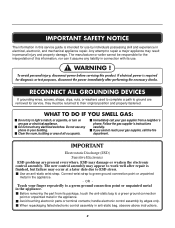
... electrical appliance. Before removing the part from a neighbor's phone. To avoid personal injury, disconnect power before servicing this information, nor can it assume any electrical switches. Do not use . ! Immediately call the fire department. Connect wrist strap to their original position and properly fastened. Avoid touching electronic parts or terminal contacts; WHAT TO DO IF YOU SMELL GAS: Do not try to light...
... electrical appliance. Before removing the part from a neighbor's phone. To avoid personal injury, disconnect power before servicing this information, nor can it assume any electrical switches. Do not use . ! Immediately call the fire department. Connect wrist strap to their original position and properly fastened. Avoid touching electronic parts or terminal contacts; WHAT TO DO IF YOU SMELL GAS: Do not try to light...
Service Manual
Page 4
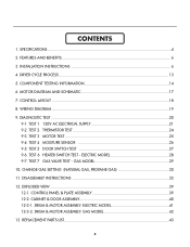
... TEST 2 THERMISTOR TEST 24 9-3. TEST 3 MOTOR TEST 25 9-4. TEST 6 HEATER SWITCH TEST - TEST 7 GAS VALVE TEST - DRYER CYCLE PROCESS ...13 5. CONTROL PANEL & PLATE ASSEMBLY 39 12-2. EXPLODED VIEW ...39 12-1. TEST 1 120V AC ELECTRICAL SUPPLY 21 9-2. CABINET & DOOR ASSEMBLY 40 12-3-1. CONTENTS 1. DRUM & MOTOR ASSEMBLY: ELECTRIC MODEL 41 12-3-2. COMPONENT TESTING INFORMATION 14 6. ELECTRIC MODEL 28 9-7. DISASSEMBLY INSTRUCTIONS 32 12. FEATURES AND BENEFITS ...6 3. CONTROL LAYOUT ...18 8. GAS MODEL 29 10. CHANGE GAS SETTING (NATURAL GAS, PROPANE GAS...
... TEST 2 THERMISTOR TEST 24 9-3. TEST 3 MOTOR TEST 25 9-4. TEST 6 HEATER SWITCH TEST - TEST 7 GAS VALVE TEST - DRYER CYCLE PROCESS ...13 5. CONTROL PANEL & PLATE ASSEMBLY 39 12-2. EXPLODED VIEW ...39 12-1. TEST 1 120V AC ELECTRICAL SUPPLY 21 9-2. CABINET & DOOR ASSEMBLY 40 12-3-1. CONTENTS 1. DRUM & MOTOR ASSEMBLY: ELECTRIC MODEL 41 12-3-2. COMPONENT TESTING INFORMATION 14 6. ELECTRIC MODEL 28 9-7. DISASSEMBLY INSTRUCTIONS 32 12. FEATURES AND BENEFITS ...6 3. CONTROL LAYOUT ...18 8. GAS MODEL 29 10. CHANGE GAS SETTING (NATURAL GAS, PROPANE GAS...
Service Manual
Page 6
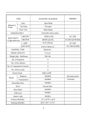
.... of Programs No. ITEM Material & Finish Color Top Plate Door Trim POWER SUPPLY ELECTRICITY CONSUMPTION MOTOR HEATER LAMP GAS VALVE CONTROL TYPE DRUM CAPACITY Weight (lbs) - of Dry Levels Sound levels Sensor Moisture Temperature Reversible Door Drum Dryer Rack Child Lock Interior Light Product (WxHxD) Packing (WxHxD) DLE2516W / DLG2526W Blue White Porcelain Silver Spray 120V/240V 60Hz (26A) 250W (4.5A... 27" x 38.74" x 29.9" 29.5" x 44.1" x 31.3" 5 REMARK AC 120V AC 240V (ELECTRIC MODEL) AC 120V AC 120V (GAS MODEL) Electrode sensor Thermistor Net/Gross No.
.... of Programs No. ITEM Material & Finish Color Top Plate Door Trim POWER SUPPLY ELECTRICITY CONSUMPTION MOTOR HEATER LAMP GAS VALVE CONTROL TYPE DRUM CAPACITY Weight (lbs) - of Dry Levels Sound levels Sensor Moisture Temperature Reversible Door Drum Dryer Rack Child Lock Interior Light Product (WxHxD) Packing (WxHxD) DLE2516W / DLG2526W Blue White Porcelain Silver Spray 120V/240V 60Hz (26A) 250W (4.5A... 27" x 38.74" x 29.9" 29.5" x 44.1" x 31.3" 5 REMARK AC 120V AC 240V (ELECTRIC MODEL) AC 120V AC 120V (GAS MODEL) Electrode sensor Thermistor Net/Gross No.
Service Manual
Page 8
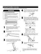
...the washer with a gas dryer in potentially unstable conditions like a mobile home. 7 Be careful not to the appliance. 5 Place the dryer on the back of the washer by placing the legs as product installation instructions describe ...washer and dryer. Failure to heed this alone! 4 Secure the side bracket to the side brackets. • Do not use a stacking kit with a screw on top of the bracket. Stacking Kit Installation Instructions To ensure safe and secure installation, please observe the instructions below. WARNING Do not attempt this warning can result in the owner's manual...
...the washer with a gas dryer in potentially unstable conditions like a mobile home. 7 Be careful not to the appliance. 5 Place the dryer on the back of the washer by placing the legs as product installation instructions describe ...washer and dryer. Failure to heed this alone! 4 Secure the side bracket to the side brackets. • Do not use a stacking kit with a screw on top of the bracket. Stacking Kit Installation Instructions To ensure safe and secure installation, please observe the instructions below. WARNING Do not attempt this warning can result in the owner's manual...
Service Manual
Page 10
... instructions under the screw of ground wire bared. you will be replaced. If this type is in order for dryer to be connecting box to center screw. 4. First, peel 5 inch (12(1.27.57c"cmm)) of appliance and connect it to a fused(21d.5"icsmc)onnect or circuit breaker (12.75c" m) 1. peel insulation back 1inch (2.5cm). and be connecting to the left and right terminal block...
... instructions under the screw of ground wire bared. you will be replaced. If this type is in order for dryer to be connecting box to center screw. 4. First, peel 5 inch (12(1.27.57c"cmm)) of appliance and connect it to a fused(21d.5"icsmc)onnect or circuit breaker (12.75c" m) 1. peel insulation back 1inch (2.5cm). and be connecting to the left and right terminal block...
Service Manual
Page 11
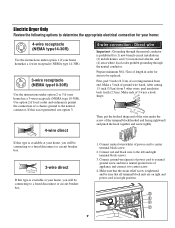
... and power cord is in the right position. Remove the neutral ground wire of the power cord to the left and right terminal block screws. 3. Make sure that the strain relief screw is tightened 10 and that all terminal block nuts are installing your local codes or ordinances do not allow the use of length in right position. Prepare minimum 5ft(1.52m) of a 3 wire connection, or you must use a 4wire connection. 1. 3-wire connection : Direct wire...
... and power cord is in the right position. Remove the neutral ground wire of the power cord to the left and right terminal block screws. 3. Make sure that the strain relief screw is tightened 10 and that all terminal block nuts are installing your local codes or ordinances do not allow the use of length in right position. Prepare minimum 5ft(1.52m) of a 3 wire connection, or you must use a 4wire connection. 1. 3-wire connection : Direct wire...
Service Manual
Page 12
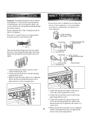
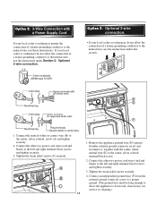
... ground. (The ground wire must be moved, if necessary, for service or cleaning.) Option 3: Optional 3-wire connection. • If your local codes or ordinances permit the connection of a frame-grounding conductor to the neutral wire, use the instructions under Section 3: Optional 3-wire connection. Tighten the strain relief screws securely. 4. Connect the other two power cord wires (red and black) to the left and right terminal block screws and tighten...
... ground. (The ground wire must be moved, if necessary, for service or cleaning.) Option 3: Optional 3-wire connection. • If your local codes or ordinances permit the connection of a frame-grounding conductor to the neutral wire, use the instructions under Section 3: Optional 3-wire connection. Tighten the strain relief screws securely. 4. Connect the other two power cord wires (red and black) to the left and right terminal block screws and tighten...
Service Manual
Page 13
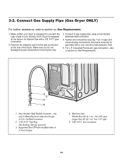
... steel connector. 4. Use only if allowed by local codes (Use Design A.G.A. Certified Connector) 2 1/8" N.P.T. Use 3/8" pipe Longer than 20' (6.1 m) - Gas Connection 12 Dryer is equipped for checking inlet gas pressure) 3 Equipment Shut-Off Valve-Installed within 6' (1.8 m) of the dryer. 3-2. Remove the shipping cap from the gas connection at the factory for gas leaks with a 3/8" N.P.T. Turn on gas and check all connections securely. Pipe Plug (for use with the type of gas in your laundry room. gas connection. 2. Connect to section on Gas Requirements...
... steel connector. 4. Use only if allowed by local codes (Use Design A.G.A. Certified Connector) 2 1/8" N.P.T. Use 3/8" pipe Longer than 20' (6.1 m) - Gas Connection 12 Dryer is equipped for checking inlet gas pressure) 3 Equipment Shut-Off Valve-Installed within 6' (1.8 m) of the dryer. 3-2. Remove the shipping cap from the gas connection at the factory for gas leaks with a 3/8" N.P.T. Turn on gas and check all connections securely. Pipe Plug (for use with the type of gas in your laundry room. gas connection. 2. Connect to section on Gas Requirements...
Service Manual
Page 20
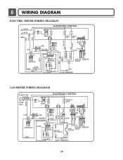
... 19 8 WIRING DIAGRAM ELECTRIC DRYER WIRING DIAGRAM L1 BLACK N WHITE L2 ELECTRONIC CONTROL 1 WH1 TRANS BL2 3 1 TAB RELAY TAB RELAY BLACK WHITE NA6 6 5 432 1 RED WHITE BACK BLUE ORANGE RED YELLOW BLUE BROWN BROWN RED SAFETY THERMOSTAT OUTER COIL INNER COIL COM NO 1 2 GRAY NC 123 DOOR SWITCH WHITE LAMP YELLOW 1 2 3 BELT SWITCH 1 2 3 7 10 MOTOR OVERLOAD PROTECTOR BLUE HEATER 2 1 2 1 MOISTURE THERMISTOR SENSOR CENTRIFUGAL SWITCH BLOWER WHITE...
... 19 8 WIRING DIAGRAM ELECTRIC DRYER WIRING DIAGRAM L1 BLACK N WHITE L2 ELECTRONIC CONTROL 1 WH1 TRANS BL2 3 1 TAB RELAY TAB RELAY BLACK WHITE NA6 6 5 432 1 RED WHITE BACK BLUE ORANGE RED YELLOW BLUE BROWN BROWN RED SAFETY THERMOSTAT OUTER COIL INNER COIL COM NO 1 2 GRAY NC 123 DOOR SWITCH WHITE LAMP YELLOW 1 2 3 BELT SWITCH 1 2 3 7 10 MOTOR OVERLOAD PROTECTOR BLUE HEATER 2 1 2 1 MOISTURE THERMISTOR SENSOR CENTRIFUGAL SWITCH BLOWER WHITE...
Service Manual
Page 21
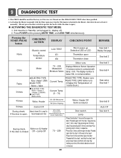
... START/PAUSE button CHECKING ACTION DISPLAY CHECKING POINT REMARK None Electric control & Temperature sensor LQC TEST tE1 tE2 Won't power up Detective LED or LCD Thermistor open . 9 DIAGNOSTIC TEST 1. Current Temp. (5 ~ 70) ELECTRIC TYPE: Heater runs GAS TYPE: GAS Valve runs (Display the Temperature of Inside drum.) 4 times Motor, Heater 50~230 Measured "SE"(Error Display) Motor, Heater Off Semi-conductor 5 times Control Off During check, If the door is open ) ACTIVATING THE DIAGNOSTIC TEST MODE 1. Off + Lamp Off 70 ~ 239 • Press Start button 1 time and then open...
... START/PAUSE button CHECKING ACTION DISPLAY CHECKING POINT REMARK None Electric control & Temperature sensor LQC TEST tE1 tE2 Won't power up Detective LED or LCD Thermistor open . 9 DIAGNOSTIC TEST 1. Current Temp. (5 ~ 70) ELECTRIC TYPE: Heater runs GAS TYPE: GAS Valve runs (Display the Temperature of Inside drum.) 4 times Motor, Heater 50~230 Measured "SE"(Error Display) Motor, Heater Off Semi-conductor 5 times Control Off During check, If the door is open ) ACTIVATING THE DIAGNOSTIC TEST MODE 1. Off + Lamp Off 70 ~ 239 • Press Start button 1 time and then open...
Service Manual
Page 22
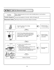
... 1 Check the outlet, is properly connected. NO • Check the fuse or circuit breaker. • Check if Power NO Cord is the voltage 110V ~ 125V AC? Test 1 120V AC Electrical supply Caution When measuring power, be sure to wear insulated gloves, to Terminal Center N (Natural) line? • Reconnect the controller. Does Power Cord N (Natural) line match to and avoid an electric shock. Trouble Symptom No power was applied to the Controller and WH1(White Wire) Is...
... 1 Check the outlet, is properly connected. NO • Check the fuse or circuit breaker. • Check if Power NO Cord is the voltage 110V ~ 125V AC? Test 1 120V AC Electrical supply Caution When measuring power, be sure to wear insulated gloves, to Terminal Center N (Natural) line? • Reconnect the controller. Does Power Cord N (Natural) line match to and avoid an electric shock. Trouble Symptom No power was applied to the Controller and WH1(White Wire) Is...
Service Manual
Page 25
... the range of Power cord with metal to the 6 pin connector's Pin (Blue Wire) and Pin (Orange Wire) to turn off, or remains on. YES • Check if Control and the 6 pin connector are properly connected. • Replace Controller. YES Check Harness-linking connector. During operation, Heater would not turn Power off , measure the resistance. Difference between terminals after separating Harness NO From Thermistor assembly Connector. • Replace Thermistor. Measurement Condition After turning Power off , and...
... the range of Power cord with metal to the 6 pin connector's Pin (Blue Wire) and Pin (Orange Wire) to turn off, or remains on. YES • Check if Control and the 6 pin connector are properly connected. • Replace Controller. YES Check Harness-linking connector. During operation, Heater would not turn Power off , measure the resistance. Difference between terminals after separating Harness NO From Thermistor assembly Connector. • Replace Thermistor. Measurement Condition After turning Power off , and...
Service Manual
Page 26
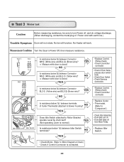
No Heater will function; NO Is resistance below 1Ω between Idler Switch terminals? Measure while door is closed . YES (Not operating Lever is normal.) Is resistance below 3Ω between terminals of Power cord with earth line.) Trouble Symptom Drum will not rotate; NO YES • Replace Control. (Relay check) • Check Controller connector. • Replace Outlet • Thermostat. (Refer to 'Component') • Check Idler Assembly. • Drum Belt cuts off • Drum Belt takes off , and...
No Heater will function; NO Is resistance below 1Ω between Idler Switch terminals? Measure while door is closed . YES (Not operating Lever is normal.) Is resistance below 3Ω between terminals of Power cord with earth line.) Trouble Symptom Drum will not rotate; NO YES • Replace Control. (Relay check) • Check Controller connector. • Replace Outlet • Thermostat. (Refer to 'Component') • Check Idler Assembly. • Drum Belt cuts off • Drum Belt takes off , and...
Service Manual
Page 27
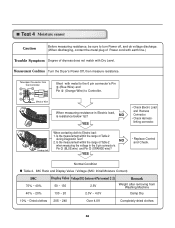
... after removing from the Controller. Test 4 Moisture sensor Caution Before measuring resistance, be sure to turn Power off, and do voltage discharge. (When discharging, contact the metal plug of Power cord with earth line.) Trouble Symptom Degree of dryness does not match with metal to the 6 pin connector's Pin (Blue Wire) and Pin (Orange Wire) to Electro load: 1. Take 6pin Connector from Washing Machine Damp Dry 10% ~ Dried clothes...
... after removing from the Controller. Test 4 Moisture sensor Caution Before measuring resistance, be sure to turn Power off, and do voltage discharge. (When discharging, contact the metal plug of Power cord with earth line.) Trouble Symptom Degree of dryness does not match with metal to the 6 pin connector's Pin (Blue Wire) and Pin (Orange Wire) to Electro load: 1. Take 6pin Connector from Washing Machine Damp Dry 10% ~ Dried clothes...
Service Manual
Page 28
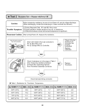
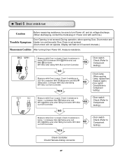
... 1 Ω between BL2- (Yellow wire) and WH1- (White wire) after taking Connector WH1,BL2 out from Controller. YES • Door switch Check (Refer to Component testing.) • Check Lamp. (When opening Door, Drum motor and Trouble Symptom Heater run continuously) Door Close is not sensed. (Drum motor will flash at 0.5 second intervals.) Measurement Condition After turning Dryer Power Off, measure resistance. YES • Door switch Check (Refer to Component testing.) Measure while Door is open . Check it resistance is below...
... 1 Ω between BL2- (Yellow wire) and WH1- (White wire) after taking Connector WH1,BL2 out from Controller. YES • Door switch Check (Refer to Component testing.) • Check Lamp. (When opening Door, Drum motor and Trouble Symptom Heater run continuously) Door Close is not sensed. (Drum motor will flash at 0.5 second intervals.) Measurement Condition After turning Dryer Power Off, measure resistance. YES • Door switch Check (Refer to Component testing.) Measure while Door is open . Check it resistance is below...
Service Manual
Page 29
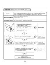
...-Limit Thermostat). Check Harness-linking Connector. 28 Test 6 Heater switch test - Drying time takes longer. YES Check Controller. TH3 TH2 1. NO YES • Replace TH2 (Safety Thermostat). Check Motor. Check if the value of Power cord with earth line.) Trouble Symptom While operating, Heating will not work. Electric Type Caution Before measuring resistance, be sure to turn Power off , measure the resistance. Is resistance between Heater terminal and below 9 ~ 11Ω? Is resistance between Heater terminal and below 18...
...-Limit Thermostat). Check Harness-linking Connector. 28 Test 6 Heater switch test - Drying time takes longer. YES Check Controller. TH3 TH2 1. NO YES • Replace TH2 (Safety Thermostat). Check Motor. Check if the value of Power cord with earth line.) Trouble Symptom While operating, Heating will not work. Electric Type Caution Before measuring resistance, be sure to turn Power off , measure the resistance. Is resistance between Heater terminal and below 9 ~ 11Ω? Is resistance between Heater terminal and below 18...
Service Manual
Page 30
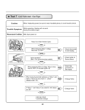
...;? Trouble Symptom While operating, Heating will not work. Measurement Condition With dryer power on Valve 1 and Valve 2, Valves are Off? NO YES • Change Valve • Harness check • Controller change 29 Gas Type Caution When measuring power, be sure to wear insulated gloves, to avoid electric shock. YES (Measure after Igniter off) YES NO • Check Gas connection or Gas supply When measuring terminal resistance on Valve 1 Igniter Valve 2 Power On & Start (Normal Cycle) NO When measuring Valve...
...;? Trouble Symptom While operating, Heating will not work. Measurement Condition With dryer power on Valve 1 and Valve 2, Valves are Off? NO YES • Change Valve • Harness check • Controller change 29 Gas Type Caution When measuring power, be sure to wear insulated gloves, to avoid electric shock. YES (Measure after Igniter off) YES NO • Check Gas connection or Gas supply When measuring terminal resistance on Valve 1 Igniter Valve 2 Power On & Start (Normal Cycle) NO When measuring Valve...
Service Manual
Page 31
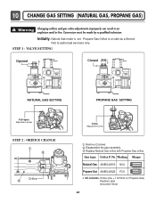
... Remove 2 screws. Replace Natural Gas orifice with Propane Gas orifice. Initially, Natural Gas mode is on sale as a Service Part to authorized servicers only. 10 CHANGE GAS SETTING (NATURAL GAS, PROPANE GAS) ! Warning Changing orifices and gas valve adjustments improperly can result in an explosion and/or fire. Conversion must be made by a qualified technician. Gas type Orifice P/No Marking Shape Natural Gas 4948EL4001B NCU Propane Gas 4948EL4002B PCU Kit contents: Orifice (Dia. = 1.613mm, for Propane Gas) Replace Label Instruction Sheet 30 Disassemble the pipe assembly...
... Remove 2 screws. Replace Natural Gas orifice with Propane Gas orifice. Initially, Natural Gas mode is on sale as a Service Part to authorized servicers only. 10 CHANGE GAS SETTING (NATURAL GAS, PROPANE GAS) ! Warning Changing orifices and gas valve adjustments improperly can result in an explosion and/or fire. Conversion must be made by a qualified technician. Gas type Orifice P/No Marking Shape Natural Gas 4948EL4001B NCU Propane Gas 4948EL4002B PCU Kit contents: Orifice (Dia. = 1.613mm, for Propane Gas) Replace Label Instruction Sheet 30 Disassemble the pipe assembly...
Service Manual
Page 44
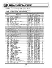
... A110 PANEL, CONTROL A130 PWB (PCB) ASSEMBLY 3720EL0002A 3720EL0002A 6871EC1121C 6871EC1121C A120 PWB (PCB) ASSEMBLY, DISPLAY A700 RACK A800 SIDE VENTING KIT 6871EC1120A 6871EC1120A 3750EL1001B 3750EL1001B 383EEL9001B 383EEL9001B 43 QTY 1 1 2 2 4 1 1 1 1 1 1 1 1 1 2 1 1 1 1 1 2 3 1 1 1 2 1 1 2 1 1 1 2 1 1 1 1 1 1 1 1 1 1 1 1 1 13 REPLACEMENT PARTS LIST CAUTION: Before replacing any of these components, read the safety precautions in this manual. ¡Æ Note: S(Safety Parts), AL (Alternative parts) LG MODEL: TD-V10062E, TD-V10060E AL LOC Description Model P/No DLE2512W...
... A110 PANEL, CONTROL A130 PWB (PCB) ASSEMBLY 3720EL0002A 3720EL0002A 6871EC1121C 6871EC1121C A120 PWB (PCB) ASSEMBLY, DISPLAY A700 RACK A800 SIDE VENTING KIT 6871EC1120A 6871EC1120A 3750EL1001B 3750EL1001B 383EEL9001B 383EEL9001B 43 QTY 1 1 2 2 4 1 1 1 1 1 1 1 1 1 2 1 1 1 1 1 2 3 1 1 1 2 1 1 2 1 1 1 2 1 1 1 1 1 1 1 1 1 1 1 1 1 13 REPLACEMENT PARTS LIST CAUTION: Before replacing any of these components, read the safety precautions in this manual. ¡Æ Note: S(Safety Parts), AL (Alternative parts) LG MODEL: TD-V10062E, TD-V10060E AL LOC Description Model P/No DLE2512W...


