
Service Manual
Page 1
http://biz.LGservice.com Dehumidifier SERVICE MANUAL MODEL: DH30 DH40 DH50 DH50E DH50EL DH65EL DHR-3030 DHE-3031 DHR-4030 DHE-4031 DHR-5030 CAUTION - ONLY FOR AUTHORIZED SERVICE. BEFORE SERVICING THE UNIT, READ THE SAFETY PRECAUTIONS IN THIS MANUAL. -
http://biz.LGservice.com Dehumidifier SERVICE MANUAL MODEL: DH30 DH40 DH50 DH50E DH50EL DH65EL DHR-3030 DHE-3031 DHR-4030 DHE-4031 DHR-5030 CAUTION - ONLY FOR AUTHORIZED SERVICE. BEFORE SERVICING THE UNIT, READ THE SAFETY PRECAUTIONS IN THIS MANUAL. -
Service Manual
Page 2
CONTENTS 1. CIRCUIT DIAGRAM 8 3. DISASSEMBLY INSTRUCTIONS 3.1 MECHANICAL PARTS 13 3.1.1 BUCKET AND AIR FILTER 13 3.1.2 FRONT CASE AND TOP COVER 13 3.1.3 CABINET AND CONTROL BOX 13 3.2 CONTROL PARTS 14 3.2.1 POWER CORD ASSEMBLY 14 3.2.2 SENSOR ASSEMBLY 14 3.2.3 PWB(PCB) ASSEMBLY, MAIN 14 3.2.4 CAPACITOR 14 3.2.5 MICRO SWITCH ASSEMBLY 14 3.2.6 COIL ASSEMBLY, SOLENOID 15 3.2.7 CONTROL PANEL 15 3.2.8 HOUSING ASSEMBLY, FAN AND MOTOR 16 3.2.9 DRAIN PAN 16 3.3 REFRIGERATING CYCLE 17 3.3.1 CONDENSER, EVAPORATOR AND CAPILLARY TUBE 17 3.3.2 PTC OR OVERLOAD ...
CONTENTS 1. CIRCUIT DIAGRAM 8 3. DISASSEMBLY INSTRUCTIONS 3.1 MECHANICAL PARTS 13 3.1.1 BUCKET AND AIR FILTER 13 3.1.2 FRONT CASE AND TOP COVER 13 3.1.3 CABINET AND CONTROL BOX 13 3.2 CONTROL PARTS 14 3.2.1 POWER CORD ASSEMBLY 14 3.2.2 SENSOR ASSEMBLY 14 3.2.3 PWB(PCB) ASSEMBLY, MAIN 14 3.2.4 CAPACITOR 14 3.2.5 MICRO SWITCH ASSEMBLY 14 3.2.6 COIL ASSEMBLY, SOLENOID 15 3.2.7 CONTROL PANEL 15 3.2.8 HOUSING ASSEMBLY, FAN AND MOTOR 16 3.2.9 DRAIN PAN 16 3.3 REFRIGERATING CYCLE 17 3.3.1 CONDENSER, EVAPORATOR AND CAPILLARY TUBE 17 3.3.2 PTC OR OVERLOAD ...
Service Manual
Page 3
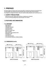
...; Removable & large capacity bucket. • Washable air filter • Two-speed fan • Drain hose connection. • Low temperature operation (DH5OEL/DH65EL) 1.2.2 DIMENSIONS (mm/in) 385 (15 3/16) 340 (13 6/16) 385 (15 3/16) 340 (13 6/16) n • 30/40 Pints Model Figure 1 -3- 50/65 Pints Model The refrigerant is charged at the factory. PREFACE This Service Manual provides various service information, including the mechanical and electrical parts. This dehumidifier was manufactured and assembled...
...; Removable & large capacity bucket. • Washable air filter • Two-speed fan • Drain hose connection. • Low temperature operation (DH5OEL/DH65EL) 1.2.2 DIMENSIONS (mm/in) 385 (15 3/16) 340 (13 6/16) 385 (15 3/16) 340 (13 6/16) n • 30/40 Pints Model Figure 1 -3- 50/65 Pints Model The refrigerant is charged at the factory. PREFACE This Service Manual provides various service information, including the mechanical and electrical parts. This dehumidifier was manufactured and assembled...
Service Manual
Page 4
... CAPACITY (Pints/24hrs) 30 40 50 CONTROL PANEL MECHANICAL TYPE DH30, DHR-3030 DH40, DHR-4030 DH50, DHR-5030 ELECTRONIC TYPE DHE-3031 DHE-4031 DH50E, DH50EL 65 DH65EL 1.4 SPECIFICATIONS ITEMS MODELS CAPACITY (Pints/24hrs) DH30 DHR-3030 DHE-3031 30 DH40 DHR-4030 DHE-4031 40 DH50 DHR-5030 DH5OE DH5OEL* 50 DH65EL* 65 POWER SUPPLY (Phase, V, Hz) 10, 115V, 60Hz REFRIGERANT...
... CAPACITY (Pints/24hrs) 30 40 50 CONTROL PANEL MECHANICAL TYPE DH30, DHR-3030 DH40, DHR-4030 DH50, DHR-5030 ELECTRONIC TYPE DHE-3031 DHE-4031 DH50E, DH50EL 65 DH65EL 1.4 SPECIFICATIONS ITEMS MODELS CAPACITY (Pints/24hrs) DH30 DHR-3030 DHE-3031 30 DH40 DHR-4030 DHE-4031 40 DH50 DHR-5030 DH5OE DH5OEL* 50 DH65EL* 65 POWER SUPPLY (Phase, V, Hz) 10, 115V, 60Hz REFRIGERANT...

Service Manual
Page 5
... first use the dehumidifier, turn the humidity control to a higher setting. Use the dehumidifier as long as excess moisture is pressed, the Timer indicator lights shift as follows: Continuous On 4 2 Hr. The cycle repeats until you change the setting. • When Timer button is present. In these cases the Water Level Control Switch shuts off completely for 2 or 4 hours. Power • Operation starts when this button to select type of humidity condition. • 35% - 70% setting: Dehumidifier runs on...
... first use the dehumidifier, turn the humidity control to a higher setting. Use the dehumidifier as long as excess moisture is pressed, the Timer indicator lights shift as follows: Continuous On 4 2 Hr. The cycle repeats until you change the setting. • When Timer button is present. In these cases the Water Level Control Switch shuts off completely for 2 or 4 hours. Power • Operation starts when this button to select type of humidity condition. • 35% - 70% setting: Dehumidifier runs on...
Service Manual
Page 6
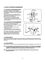
... case, please check your room temperature conditions and stop the unit. Dry Air Out Bucket Condenser Motor Evaporator Fan Humid Air In 00" .0" 0 0 Compressor Drain Connection Figure 4} 1 12" Figure 5 } 1.6.3 MICRO SWITCH The micro switch assembly, which is normal for good air circulation. (See Figure 5) ■ The dehumidifier must be operated at least 12 inches of space on the cooling coils, the unit will continuously cycle up on all doors, windows and other outside...
... case, please check your room temperature conditions and stop the unit. Dry Air Out Bucket Condenser Motor Evaporator Fan Humid Air In 00" .0" 0 0 Compressor Drain Connection Figure 4} 1 12" Figure 5 } 1.6.3 MICRO SWITCH The micro switch assembly, which is normal for good air circulation. (See Figure 5) ■ The dehumidifier must be operated at least 12 inches of space on the cooling coils, the unit will continuously cycle up on all doors, windows and other outside...
Service Manual
Page 7
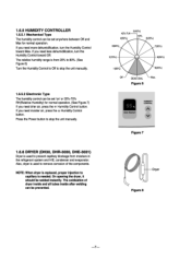
..., condenser and evaporator. Figure 6 C_I Cl % Auto Restart HUMIDITY CONTROL V Figure 7 Dryer Figure 8 If you need more dehumidification, turn the Humidity Control toward Max. If you need moister air, press the A Humidity Control button. The oxidization of the components. The relative humidity range is used to stop the unit manually. 1.6.5.2 Electronic Type The humidity control can be set anywhere between Off and Max for normal operation. (See Figure 7) If you need drier air, press the v Humidity Control button. 1.6.5 HUMIDITY CONTROLLER 1.6.5.1 Mechanical...
..., condenser and evaporator. Figure 6 C_I Cl % Auto Restart HUMIDITY CONTROL V Figure 7 Dryer Figure 8 If you need more dehumidification, turn the Humidity Control toward Max. If you need moister air, press the A Humidity Control button. The oxidization of the components. The relative humidity range is used to stop the unit manually. 1.6.5.2 Electronic Type The humidity control can be set anywhere between Off and Max for normal operation. (See Figure 7) If you need drier air, press the v Humidity Control button. 1.6.5 HUMIDITY CONTROLLER 1.6.5.1 Mechanical...
Service Manual
Page 8
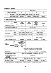
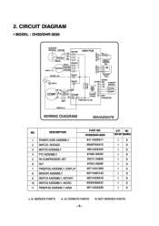
... _,4 RY-COMP BL 4 0 3 BUCKET m CN-SEN WI -< - N: NOT SERVICE PARTS Zv'' - HUMIDITY CONTROL SNV Imi cn 5 Z 0 0 0 0 0 0 BUCKET FULL E , GN/YL CEN lAC2 M 6 :3 BK COMP. DESCRIPTION 1 POWER CORD ASSEMBLY 2 SWITCH, ROCKER 3 MOTOR ASSEMBLY 4 PTC ASSEMBLY 5 RE-COMPRESSOR, SET 6 0LP 7 PWB(PCB) ASSEMBLY, DISPLAY 8 SENSOR ASSEMBLY 9 SWITCH ASSEMBLY, ROTARY 10 SWITCH ASSEMBLY, MICRO 11 PWB(PCB) ASSEMBLY, MAIN PART NO. I, >z a HUMIDITY SENSOR 0 _r' 0 POWER TRANS THERMISTOR OLP FUSE 250V T3.15A BK(BR) (L) WIRING DIAGRAM 3854A20247B .1 NO. 2. c ., 0 0 °...
... _,4 RY-COMP BL 4 0 3 BUCKET m CN-SEN WI -< - N: NOT SERVICE PARTS Zv'' - HUMIDITY CONTROL SNV Imi cn 5 Z 0 0 0 0 0 0 BUCKET FULL E , GN/YL CEN lAC2 M 6 :3 BK COMP. DESCRIPTION 1 POWER CORD ASSEMBLY 2 SWITCH, ROCKER 3 MOTOR ASSEMBLY 4 PTC ASSEMBLY 5 RE-COMPRESSOR, SET 6 0LP 7 PWB(PCB) ASSEMBLY, DISPLAY 8 SENSOR ASSEMBLY 9 SWITCH ASSEMBLY, ROTARY 10 SWITCH ASSEMBLY, MICRO 11 PWB(PCB) ASSEMBLY, MAIN PART NO. I, >z a HUMIDITY SENSOR 0 _r' 0 POWER TRANS THERMISTOR OLP FUSE 250V T3.15A BK(BR) (L) WIRING DIAGRAM 3854A20247B .1 NO. 2. c ., 0 0 °...
Service Manual
Page 9
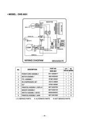
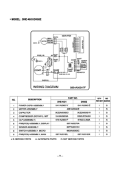
ASSEMBLY 4 RE-COMPRESSOR, SET 5 OLP 6 PWB(PCB) ASSEMBLY, DISPLAY 7 SENSOR ASSEMBLY 8 SWITCH ASSEMBLY, MICRO 9 PWB(PCB) ASSEMBLY, MAIN PART NO. • MODEL : DHE-3031 ( • GN/YL = CN-FAN BK H MOTOR RD LO OR COM MAIN PCB DISPLAY PCB O_i cc- DESCRIPTION 1 POWER CORD ASSEMBLY 2 MOTOR ASSEMBLY 3 PTC. S5' C OLP 3 BK 4 RY-COMP BL 4 3 POWER TRANS FUSE 250V T3.15A THERMISTOR BK(BR) (L) WIRING DIAGRAM 3854A20247E NO. DHE-3031 6411A20001Y 4681A20040E 6748C-0003D...
ASSEMBLY 4 RE-COMPRESSOR, SET 5 OLP 6 PWB(PCB) ASSEMBLY, DISPLAY 7 SENSOR ASSEMBLY 8 SWITCH ASSEMBLY, MICRO 9 PWB(PCB) ASSEMBLY, MAIN PART NO. • MODEL : DHE-3031 ( • GN/YL = CN-FAN BK H MOTOR RD LO OR COM MAIN PCB DISPLAY PCB O_i cc- DESCRIPTION 1 POWER CORD ASSEMBLY 2 MOTOR ASSEMBLY 3 PTC. S5' C OLP 3 BK 4 RY-COMP BL 4 3 POWER TRANS FUSE 250V T3.15A THERMISTOR BK(BR) (L) WIRING DIAGRAM 3854A20247E NO. DHE-3031 6411A20001Y 4681A20040E 6748C-0003D...
Service Manual
Page 10
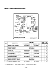
CN-AC2 El 0_ H BUCKET CN-SEN SM HUMIDITY - DESCRIPTION 1 POWER CORD ASSEMBLY 2 SWITCH, ROCKER 3 MOTOR ASSEMBLY 4 CAPACITOR 5 COMPRESSOR (ROTARY), SET 6 OLP (ASSEMBLY) 7 PWB(PCB) ASSEMBLY, DISPLAY 8 SENSOR ASSEMBLY 9 SWITCH ASSEMBLY, ROTARY 10 SWITCH ASSEMBLY, MICRO 11 PWB(PCB) ASSEMBLY, MAIN PART NO. DH40/DHR-4030 DH50/DHR-5030 6411A20001Y 6411A20001Z 6600FX5001E 4681A20040E 0CZZA20003D 0CZZA20001R 5416A90009A 2520UCDA003 6751A20001F 6750U-L058A 6871A20169B 6877A30013G 6877A30013H 6601A30001B 6600A30003C 6871A30032A 6871A3032B Q'TY REPER SET MARKS 1 S 1 S 1...
CN-AC2 El 0_ H BUCKET CN-SEN SM HUMIDITY - DESCRIPTION 1 POWER CORD ASSEMBLY 2 SWITCH, ROCKER 3 MOTOR ASSEMBLY 4 CAPACITOR 5 COMPRESSOR (ROTARY), SET 6 OLP (ASSEMBLY) 7 PWB(PCB) ASSEMBLY, DISPLAY 8 SENSOR ASSEMBLY 9 SWITCH ASSEMBLY, ROTARY 10 SWITCH ASSEMBLY, MICRO 11 PWB(PCB) ASSEMBLY, MAIN PART NO. DH40/DHR-4030 DH50/DHR-5030 6411A20001Y 6411A20001Z 6600FX5001E 4681A20040E 0CZZA20003D 0CZZA20001R 5416A90009A 2520UCDA003 6751A20001F 6750U-L058A 6871A20169B 6877A30013G 6877A30013H 6601A30001B 6600A30003C 6871A30032A 6871A3032B Q'TY REPER SET MARKS 1 S 1 S 1...
Service Manual
Page 11
...-FAN BK HI MAIN PCB MOTOR RD LOW OR(COM) aCl) 0 0 z O_i cc- WH(BL) (N) BR CN-AC1 GN/YL co R C CN-AC2 H BUCKET CN-SEN S/W HUMIDITY SENSOR COMR s C RD RY-COMP BL 4 3 POWER TRANS OLP FUSE 250V T3.15A THERMISTOR BK(BR) (L) WIRING DIAGRAM 3854A20247F i NO. DESCRIPTION 1 POWER CORD ASSEMBLY 2 MOTOR ASSEMBLY 3 CAPACITOR 4 COMPRESSOR (ROTARY), SET 5 OLP (ASSEMBLY) 6 PWB(PCB) ASSEMBLY, DISPLAY 7 SENSOR ASSEMBLY 8 SWITCH ASSEMBLY, MICRO 9 PWB(PCB) ASSEMBLY, MAIN PART...
...-FAN BK HI MAIN PCB MOTOR RD LOW OR(COM) aCl) 0 0 z O_i cc- WH(BL) (N) BR CN-AC1 GN/YL co R C CN-AC2 H BUCKET CN-SEN S/W HUMIDITY SENSOR COMR s C RD RY-COMP BL 4 3 POWER TRANS OLP FUSE 250V T3.15A THERMISTOR BK(BR) (L) WIRING DIAGRAM 3854A20247F i NO. DESCRIPTION 1 POWER CORD ASSEMBLY 2 MOTOR ASSEMBLY 3 CAPACITOR 4 COMPRESSOR (ROTARY), SET 5 OLP (ASSEMBLY) 6 PWB(PCB) ASSEMBLY, DISPLAY 7 SENSOR ASSEMBLY 8 SWITCH ASSEMBLY, MICRO 9 PWB(PCB) ASSEMBLY, MAIN PART...
Service Manual
Page 12
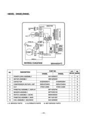
... (L) WIRING DIAGRAM 3854A20247C NO. DH5OEL DH65EL 6411A20001Z 4681A20040E 0CZZA20001R 6120AR2359V 2520UCDA003 2520UCDA004 6750U-L058A 6750U-L048A 6871A20279A 6877A30013H 6600A30003C 6871A20162E 6421A20003E S: SERVICE PARTS A: ALTERNATE PARTS N: NOT SERVICE PARTS Q'TY REPER SET MARKS 1 S 1 S 1 S 1 S 1 S 1 S 1 S 1 S 1 S 1 S -12- DESCRIPTION 1 POWER CORD ASSEMBLY 2 MOTOR ASSEMBLY 3 CAPACITOR 4 COMPRESSOR (ROTARY), SET 5 OLP. 6 PWB(PCB) ASSEMBLY, DISPLAY 7 SENSOR ASSEMBLY 8 SWITCH ASSEMBLY, MICRO 9 PWB(PCB) ASSEMBLY, MAIN 10 COIL ASSEMBLY, SOLENOID PART...
... (L) WIRING DIAGRAM 3854A20247C NO. DH5OEL DH65EL 6411A20001Z 4681A20040E 0CZZA20001R 6120AR2359V 2520UCDA003 2520UCDA004 6750U-L058A 6750U-L048A 6871A20279A 6877A30013H 6600A30003C 6871A20162E 6421A20003E S: SERVICE PARTS A: ALTERNATE PARTS N: NOT SERVICE PARTS Q'TY REPER SET MARKS 1 S 1 S 1 S 1 S 1 S 1 S 1 S 1 S 1 S 1 S -12- DESCRIPTION 1 POWER CORD ASSEMBLY 2 MOTOR ASSEMBLY 3 CAPACITOR 4 COMPRESSOR (ROTARY), SET 5 OLP. 6 PWB(PCB) ASSEMBLY, DISPLAY 7 SENSOR ASSEMBLY 8 SWITCH ASSEMBLY, MICRO 9 PWB(PCB) ASSEMBLY, MAIN 10 COIL ASSEMBLY, SOLENOID PART...
Service Manual
Page 13
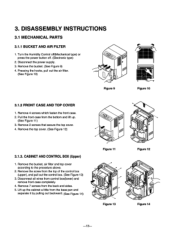
Remove the bucket. (See Figure 9) 4. Disconnect all wires from the back and sides. 5. Lift up . (See Figure 11) 3. Turn the Humidity Control off(Mechanical type) or press the power button off. (Electronic type) ,g- 2. CABINET AND CONTROL BOX (Upper) 1. O Figure 13 Figure 14 -13- 3. DISASSEMBLY INSTRUCTIONS 3.1 MECHANICAL PARTS 3.1.1 BUCKET AND AIR FILTER 1. Pressing the hooks, pull out the air filter. (See Figure 10) Figure 9 Figure 10 3.1.2 FRONT CASE AND TOP COVER 1. Remove 7 screws from control box...
Remove the bucket. (See Figure 9) 4. Disconnect all wires from the back and sides. 5. Lift up . (See Figure 11) 3. Turn the Humidity Control off(Mechanical type) or press the power button off. (Electronic type) ,g- 2. CABINET AND CONTROL BOX (Upper) 1. O Figure 13 Figure 14 -13- 3. DISASSEMBLY INSTRUCTIONS 3.1 MECHANICAL PARTS 3.1.1 BUCKET AND AIR FILTER 1. Pressing the hooks, pull out the air filter. (See Figure 10) Figure 9 Figure 10 3.1.2 FRONT CASE AND TOP COVER 1. Remove 7 screws from control box...
Service Manual
Page 14
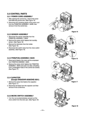
... Figure 18 Disconnect the switch wires from the drain pan. (See Figure 18) -14- Turn the nut counterclockwise and pull out the micro switch from the micro switch assembly. (See Figure 16) 3.2.3 PWB(PCB) ASSEMBLY, MAIN 1. 3.2 CONTROL PARTS 3.2.1 POWER CORD ASSEMBLY 1. Remove the screw that holds the ground wire. (See Figure 15) 2. Disconnect the remaining leads of the motor and the compressor from 2 rectangular holes of...
... Figure 18 Disconnect the switch wires from the drain pan. (See Figure 18) -14- Turn the nut counterclockwise and pull out the micro switch from the micro switch assembly. (See Figure 16) 3.2.3 PWB(PCB) ASSEMBLY, MAIN 1. 3.2 CONTROL PARTS 3.2.1 POWER CORD ASSEMBLY 1. Remove the screw that holds the ground wire. (See Figure 15) 2. Disconnect the remaining leads of the motor and the compressor from 2 rectangular holes of...
Service Manual
Page 15
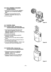
...) ASSEMBLY, DISPLAY after turning over both sides of the COIL ASSEMBLY, SOLENOID from PWB(PCB) ASSEMBLY, MAIN (3.1.3). 2. Remove 5 screws that fastens the COIL ASSEMBLY, SOLENOID. (See Figure 19) 3. 3.2.6 COIL ASSEMBLY, SOLENOID (DH5OEL/DH65EL) 1. Remove the screw that secure the PWB(PCB) ASSEMBLY, DISPLAY to the display cover. -15- Remove the knob of the rotary switch by pushing the hooks on the both hooks of the rocker switch, SWITCH ASSEMBLY, ROTARY and PWB(PCB) ASSEMBLY, DISPLAY from...
...) ASSEMBLY, DISPLAY after turning over both sides of the COIL ASSEMBLY, SOLENOID from PWB(PCB) ASSEMBLY, MAIN (3.1.3). 2. Remove 5 screws that fastens the COIL ASSEMBLY, SOLENOID. (See Figure 19) 3. 3.2.6 COIL ASSEMBLY, SOLENOID (DH5OEL/DH65EL) 1. Remove the screw that secure the PWB(PCB) ASSEMBLY, DISPLAY to the display cover. -15- Remove the knob of the rotary switch by pushing the hooks on the both hooks of the rocker switch, SWITCH ASSEMBLY, ROTARY and PWB(PCB) ASSEMBLY, DISPLAY from...

Service Manual
Page 17
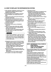
...'N, 4O' Figure 26 41t.4 .*; ,t1 Figure 27 Figure 28 Using Recipro Compressor model Figure 29 Using Rotary Compressor models -17- 3.3 REFRIGERATING CYCLE 3.3.1 CONDENSER, EVAPORATOR AND CAPILLARY TUBE 1. Remove the insulation on the Heater/Evaporator (H/E) assembly 2. Unbraze the capillary tube at the compressor connections. 3. Disconnect the lead wire from the orifice. (See Figure 27) 7. Discharge the refrigerant by using a refrigerant Recovery System. 2. Lift the H/E and open the H/E around...
...'N, 4O' Figure 26 41t.4 .*; ,t1 Figure 27 Figure 28 Using Recipro Compressor model Figure 29 Using Rotary Compressor models -17- 3.3 REFRIGERATING CYCLE 3.3.1 CONDENSER, EVAPORATOR AND CAPILLARY TUBE 1. Remove the insulation on the Heater/Evaporator (H/E) assembly 2. Unbraze the capillary tube at the compressor connections. 3. Disconnect the lead wire from the orifice. (See Figure 27) 7. Discharge the refrigerant by using a refrigerant Recovery System. 2. Lift the H/E and open the H/E around...
Service Manual
Page 18
... of refrigerant R22. If water quantity is still closed , stop the vacuum pump. 4) Remove the hose from foaming and being drawn into the pinch-off valve B and allow the proper charge to the pinch-off connection. Valve B is over 150mg, it . This will keep oil from the vacuum pump and place it to drop. CHECK THE SPECIFICATION LABEL...
... of refrigerant R22. If water quantity is still closed , stop the vacuum pump. 4) Remove the hose from foaming and being drawn into the pinch-off valve B and allow the proper charge to the pinch-off connection. Valve B is over 150mg, it . This will keep oil from the vacuum pump and place it to drop. CHECK THE SPECIFICATION LABEL...
Service Manual
Page 20
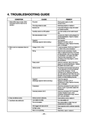
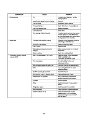
... not defrost control. 4. Install plug properly or replace it . Check the wire connections; The Defrost Control senses frost build-up on the evaporator coil and automatically shuts off . The fan continues to the wiring diagram, correct the connections. When the coil is defective. Turn dehumidifier off the compressor. Clean evaporator and/or condenser assembly Clean it . Check Motor, repair or replace it . Humidity control is open . (If the compressor temperature is dirty. Connect wire. Replace if shorted, open , or damaged. Replace the switch if the circuit is at...
... not defrost control. 4. Install plug properly or replace it . Check the wire connections; The Defrost Control senses frost build-up on the evaporator coil and automatically shuts off . The fan continues to the wiring diagram, correct the connections. When the coil is defective. Turn dehumidifier off the compressor. Clean evaporator and/or condenser assembly Clean it . Check Motor, repair or replace it . Humidity control is open . (If the compressor temperature is dirty. Connect wire. Replace if shorted, open , or damaged. Replace the switch if the circuit is at...
Service Manual
Page 21
.... Check line voltage. Repair. Check the terminals. Tube hits frame. Connection may be turned off. Heat Exchange clogged with dust or dirt. Check micro switch and float. Move dehumidifier for emptying. Test the capacitor. Replace if open. (If the compressor temperature is not installed properly. Loose set screws Worn bearings of the drain pan. Motor Bad PTC assembly (if assembled) Short circuit or ground in bucket Water drips when bucket removed for free...
.... Check line voltage. Repair. Check the terminals. Tube hits frame. Connection may be turned off. Heat Exchange clogged with dust or dirt. Check micro switch and float. Move dehumidifier for emptying. Test the capacitor. Replace if open. (If the compressor temperature is not installed properly. Loose set screws Worn bearings of the drain pan. Motor Bad PTC assembly (if assembled) Short circuit or ground in bucket Water drips when bucket removed for free...
Service Manual
Page 23
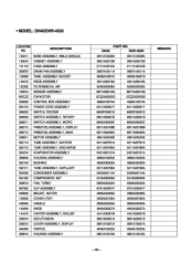
... DRAIN PAN ASSEMBLY 148380 TANK, ASSEMBLY BUCKET 149410 KNOB ASSEMBLY 152302 FILTER(MECH), AIR 162615 SENSOR ASSEMBLY WOCZZ CAPACITOR 249950 CONTROL BOX ASSEMBLY 264110 POWER CORD ASSEMBLY 266002 SWITCH, ROCKER 266003 SWITCH ASSEMBLY, ROTARY 266011 SWITCH ASSEMBLY, MICRO 268712 PWB(PCB) ASSEMBLY, DISPLAY 268714 PWB(PCB) ASSEMBLY, MAIN 346811 MOTOR ASSEMBLY 35211A TUBE ASSEMBLY, SUCTION 352113 TUBE ASSEMBLY, DISCHARGE 354210 EVAPORATOR ASSEMBLY 336600 HOUSING ASSEMBLY 550140 BUSHING 552111 TUBE ASSEMBLY, CAPILLARY 554030 CONDENSER ASSEMBLY 554160 COMPRESSOR, SET 359012 FAN...
... DRAIN PAN ASSEMBLY 148380 TANK, ASSEMBLY BUCKET 149410 KNOB ASSEMBLY 152302 FILTER(MECH), AIR 162615 SENSOR ASSEMBLY WOCZZ CAPACITOR 249950 CONTROL BOX ASSEMBLY 264110 POWER CORD ASSEMBLY 266002 SWITCH, ROCKER 266003 SWITCH ASSEMBLY, ROTARY 266011 SWITCH ASSEMBLY, MICRO 268712 PWB(PCB) ASSEMBLY, DISPLAY 268714 PWB(PCB) ASSEMBLY, MAIN 346811 MOTOR ASSEMBLY 35211A TUBE ASSEMBLY, SUCTION 352113 TUBE ASSEMBLY, DISCHARGE 354210 EVAPORATOR ASSEMBLY 336600 HOUSING ASSEMBLY 550140 BUSHING 552111 TUBE ASSEMBLY, CAPILLARY 554030 CONDENSER ASSEMBLY 554160 COMPRESSOR, SET 359012 FAN...


