
EFI Pro 16h Operations Guide
Page 5
... Hazards and Precautions 18 2.8.1 UV Ink and Solvent Precautions 18 2.8.2 UV Light Hazards 18 2.8.3 Ventilation 18 2.8.4 Storage of Combustible Materials 18 2.8.5 Fire or Explosion Risks and Precautions 19 2.8.6 Risk of Eye and Skin Irritation 19 2.8.7 Printing Media Handling and Precautions 19 2.8.8 High Voltage Dangers and Precautions 19 3.0 EFI Pro 16h Printer Overview ...20 3.1 Front...
... Hazards and Precautions 18 2.8.1 UV Ink and Solvent Precautions 18 2.8.2 UV Light Hazards 18 2.8.3 Ventilation 18 2.8.4 Storage of Combustible Materials 18 2.8.5 Fire or Explosion Risks and Precautions 19 2.8.6 Risk of Eye and Skin Irritation 19 2.8.7 Printing Media Handling and Precautions 19 2.8.8 High Voltage Dangers and Precautions 19 3.0 EFI Pro 16h Printer Overview ...20 3.1 Front...

EFI Pro 16h Operations Guide
Page 6
...Utility Overview 45 4.2.2 Settings Menu 48 4.2.3 Adding Drives 49 4.2.4 Select Files to Print Button 50 4.2.5 Image Information and Ink Use Estimates Panes 51 Conflict Message 52 4.3 EFI Pro 16h Control Window 53 4.3.1 Carriage Controls 54 4.3.2 X, Y Axes and Fence Movement Controls 55 4.3.3 Lamp Controls 56 4.3.4 ...Tab 62 Offset Tab 63 Head Voltage Tab 64 Head Temperatures Tab 65 4.3.10 EFI PLC Control Window 66 4.3.11 Printer Status Messages 67 4.3.12 EFI Pro 16h Control Window "Asleep 68 5.0 EFI Pro 16h Printer Setup ...69 5.1 Full Printer Startup From Power Down 69 5.2 Printer ...
...Utility Overview 45 4.2.2 Settings Menu 48 4.2.3 Adding Drives 49 4.2.4 Select Files to Print Button 50 4.2.5 Image Information and Ink Use Estimates Panes 51 Conflict Message 52 4.3 EFI Pro 16h Control Window 53 4.3.1 Carriage Controls 54 4.3.2 X, Y Axes and Fence Movement Controls 55 4.3.3 Lamp Controls 56 4.3.4 ...Tab 62 Offset Tab 63 Head Voltage Tab 64 Head Temperatures Tab 65 4.3.10 EFI PLC Control Window 66 4.3.11 Printer Status Messages 67 4.3.12 EFI Pro 16h Control Window "Asleep 68 5.0 EFI Pro 16h Printer Setup ...69 5.1 Full Printer Startup From Power Down 69 5.2 Printer ...

EFI Pro 16h Operations Guide
Page 7
... Boards 74 5.5 Set Media Margins 75 5.6 Setting Media Vacuum Chamber Controls 76 5.7 Set the Print Gap 77 6.0 Printing on the EFI Pro 16h ...78 6.1 Standard Printing Procedure 78 6.1.1 Start Up Printer 78 6.1.2 Verify Lamp Settings 79 6.1.3 Set the Carriage Gap 80 6.1.4 Scan... Margins in Print Files 97 Print File Margins Setup 1 97 Print File Margins Setup 2 97 7.0 Procedures for Replenishing Ink ...98 7.1 Use Remainder Ink 99 8.0 EFI Pro 16h Maintenance and Print Head Care 100 8.1 Maintenance Documentation 100 8.1.1 Maintenance Guide 100 8.1.2 Maintenance Log 100 8.2 Print Head ...
... Boards 74 5.5 Set Media Margins 75 5.6 Setting Media Vacuum Chamber Controls 76 5.7 Set the Print Gap 77 6.0 Printing on the EFI Pro 16h ...78 6.1 Standard Printing Procedure 78 6.1.1 Start Up Printer 78 6.1.2 Verify Lamp Settings 79 6.1.3 Set the Carriage Gap 80 6.1.4 Scan... Margins in Print Files 97 Print File Margins Setup 1 97 Print File Margins Setup 2 97 7.0 Procedures for Replenishing Ink ...98 7.1 Use Remainder Ink 99 8.0 EFI Pro 16h Maintenance and Print Head Care 100 8.1 Maintenance Documentation 100 8.1.1 Maintenance Guide 100 8.1.2 Maintenance Log 100 8.2 Print Head ...

EFI Pro 16h Operations Guide
Page 9
... - tenance, and general printer maintenance and care. 1.0 Introduction The EFI Pro 16h Operations Guide provides an overview of the features and functions of 9 inches [22.9 cm]. The EFI Pro 16h uses environmentally-friendly UV-curable inks to improper use while loading media and conducting other standard tasks. ...• Learn printer control software - The EFI Pro 16h can handle media widths up to 65" [165 cm...
... - tenance, and general printer maintenance and care. 1.0 Introduction The EFI Pro 16h Operations Guide provides an overview of the features and functions of 9 inches [22.9 cm]. The EFI Pro 16h uses environmentally-friendly UV-curable inks to improper use while loading media and conducting other standard tasks. ...• Learn printer control software - The EFI Pro 16h can handle media widths up to 65" [165 cm...

EFI Pro 16h Operations Guide
Page 11
...chapter explains how to safely use emergency stop the printer. Never use your EFI Pro 16h printer, including the access panels, shields, and warning labels, as well as an alternative to properly handle printer inks and fluids. Emergency stop button does the following: • Shuts off... UV lamps • Stops all safety precautions therein. • Read and sign the UV Safety Acknowledgement Form. 2.1 Emergency Stop Button(s) In case of EFI Pro 16h Figure 2-1: Emergency Stop...
...chapter explains how to safely use emergency stop the printer. Never use your EFI Pro 16h printer, including the access panels, shields, and warning labels, as well as an alternative to properly handle printer inks and fluids. Emergency stop button does the following: • Shuts off... UV lamps • Stops all safety precautions therein. • Read and sign the UV Safety Acknowledgement Form. 2.1 Emergency Stop Button(s) In case of EFI Pro 16h Figure 2-1: Emergency Stop...

EFI Pro 16h Operations Guide
Page 13
Keep all safety interlocks, covers, and guards in place and in working order. Do not operate the printer with covers or guards removed or malfunctioning interlocks. 1 Access to Carriage "Home" Compartment 2 Front Printing Shield 3 Access to Ink Supply System Compartment 4 Access to Main Vacuum Motors 5 Access to Computer Compartment Document ID: OMM-00135 Revision A 13 2.3 Front Access Panels and Shields This section illustrates the access panels and shields located on the front of the printer. 1 2 3 4 5 Figure 2-3: Printer Front Access Panels and Shields Caution!
Keep all safety interlocks, covers, and guards in place and in working order. Do not operate the printer with covers or guards removed or malfunctioning interlocks. 1 Access to Carriage "Home" Compartment 2 Front Printing Shield 3 Access to Ink Supply System Compartment 4 Access to Main Vacuum Motors 5 Access to Computer Compartment Document ID: OMM-00135 Revision A 13 2.3 Front Access Panels and Shields This section illustrates the access panels and shields located on the front of the printer. 1 2 3 4 5 Figure 2-3: Printer Front Access Panels and Shields Caution!

EFI Pro 16h Operations Guide
Page 14
.... 1 Access to Carriage X-Axis Drive System* 2 Access to Computer Compartment 3 Access to Electronic Compartment * 4 Access to Main Vacuum Motors 5 Access to Waste Bottle 6 Access to Ink Bottles and Pumps 7 Rear Carriage Access (Cooling System)* 8 Rear Printing Shield * Field Service ONLY Document ID: OMM-00135 Revision A 14
.... 1 Access to Carriage X-Axis Drive System* 2 Access to Computer Compartment 3 Access to Electronic Compartment * 4 Access to Main Vacuum Motors 5 Access to Waste Bottle 6 Access to Ink Bottles and Pumps 7 Rear Carriage Access (Cooling System)* 8 Rear Printing Shield * Field Service ONLY Document ID: OMM-00135 Revision A 14

EFI Pro 16h Operations Guide
Page 16
... Printer Safety Guide for a list of front and rear labels. 2.6 Printer Safety Labels (Front) There are numerous labels located on the EFI Pro 16h printer that they signify. 1 6 5 I 2 4 33 Figure 2-6: Front Safety Labels 1 Ink Compartment Labels 2 Wheel Lock Labels 3 Media Take-Up System Labels 4 Interlock Override Key-lock 5 Operator Station "Read Manual" Label 6 Carriage...
... Printer Safety Guide for a list of front and rear labels. 2.6 Printer Safety Labels (Front) There are numerous labels located on the EFI Pro 16h printer that they signify. 1 6 5 I 2 4 33 Figure 2-6: Front Safety Labels 1 Ink Compartment Labels 2 Wheel Lock Labels 3 Media Take-Up System Labels 4 Interlock Override Key-lock 5 Operator Station "Read Manual" Label 6 Carriage...

EFI Pro 16h Operations Guide
Page 18
...• Avoid being too close proximity to harmful UV light. 2.8.3 Ventilation Proper ventilation - If a container shows signs of Combustible Materials Inks and solvents should be off while completing maintenance tasks, especially when working with insufficient ventilation. • Operator should wear safety glasses or ...a face shield. • Operator should wear Nitrile gloves when flushing print heads, ink tubes, or when working in close to eyes and skin. All doors should be trained in using fire extinguishers and techniques for...
...• Avoid being too close proximity to harmful UV light. 2.8.3 Ventilation Proper ventilation - If a container shows signs of Combustible Materials Inks and solvents should be off while completing maintenance tasks, especially when working with insufficient ventilation. • Operator should wear safety glasses or ...a face shield. • Operator should wear Nitrile gloves when flushing print heads, ink tubes, or when working in close to eyes and skin. All doors should be trained in using fire extinguishers and techniques for...

EFI Pro 16h Operations Guide
Page 19
... printer or ink storage area. • Ensure proper use of fire extinguishers. 2.8.6 Risk of rigid media as well as roll-to operate in accordance with key protective covers opened or removed, electrical components carrying high voltage are present. The EFI Pro 16h carries high ...cement floor. However, with local electrical safety regulations per State, Province, Region, or Coun- Only qualified service technicians may service the EFI Pro 16h Electrical Systems. Follow these precautions: • Wear hand and foot safety protection gear when loading, unloading and handling media to avoid...
... printer or ink storage area. • Ensure proper use of fire extinguishers. 2.8.6 Risk of rigid media as well as roll-to operate in accordance with key protective covers opened or removed, electrical components carrying high voltage are present. The EFI Pro 16h carries high ...cement floor. However, with local electrical safety regulations per State, Province, Region, or Coun- Only qualified service technicians may service the EFI Pro 16h Electrical Systems. Follow these precautions: • Wear hand and foot safety protection gear when loading, unloading and handling media to avoid...

EFI Pro 16h Operations Guide
Page 20
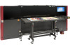
... Overview In this chapter we describe the major assemblies and sub-assemblies of the EFI Pro 16h Wide Format printer, to familiarize you with its most important components. 3.1 Front Printer Components This section illustrates the major components located on the front of ... 11 12 13 Figure 3-1: Printer Front 2 Carriage 5 Secondary Front E-Stop Button 8 Vacuum Media Belt 11 Operator Station E-Stop Button 14 Computer Compartment 3 Operator Station Monitor 6 Ink Supply Compartment 9 Front Rolled Media Handling Sys 12 USB Ports Document ID: OMM-00135 Revision A 20
... Overview In this chapter we describe the major assemblies and sub-assemblies of the EFI Pro 16h Wide Format printer, to familiarize you with its most important components. 3.1 Front Printer Components This section illustrates the major components located on the front of ... 11 12 13 Figure 3-1: Printer Front 2 Carriage 5 Secondary Front E-Stop Button 8 Vacuum Media Belt 11 Operator Station E-Stop Button 14 Computer Compartment 3 Operator Station Monitor 6 Ink Supply Compartment 9 Front Rolled Media Handling Sys 12 USB Ports Document ID: OMM-00135 Revision A 20

EFI Pro 16h Operations Guide
Page 21
Detailed information on all carriage components is provided in Section Carriage Assembly. 2 3 4 1 Figure 3-2: Carriage "Home" Compartment 1 Ink Purge Panel 4 Sweep Tray and Vacuum Knife 2 Overhead Light 3 Carriage (Covers Shown) Document ID: OMM-00135 Revision A 21 3.1.1 Carriage Home Compartment The carriage "Home" compartment contains the Ink Purge control panel, the carriage (when not printing), the overhead light, and the sweep tray and vacuum knife.
Detailed information on all carriage components is provided in Section Carriage Assembly. 2 3 4 1 Figure 3-2: Carriage "Home" Compartment 1 Ink Purge Panel 4 Sweep Tray and Vacuum Knife 2 Overhead Light 3 Carriage (Covers Shown) Document ID: OMM-00135 Revision A 21 3.1.1 Carriage Home Compartment The carriage "Home" compartment contains the Ink Purge control panel, the carriage (when not printing), the overhead light, and the sweep tray and vacuum knife.

EFI Pro 16h Operations Guide
Page 22
Pressing this button drains the contents of the cyclonic vacuum system into the waste container Document ID: OMM-00135 Revision A 22 The left purge button controls the CYMK color ink manual purging. 2. The right purge button controls the manual purge for white. 3. The Liquid Separator button controls the cyclonic vacuum pump. The Ink Purge control panel provides the following manual purge functions: 1 2 3 Figure 3-3: Ink Purge Panel 1.
Pressing this button drains the contents of the cyclonic vacuum system into the waste container Document ID: OMM-00135 Revision A 22 The left purge button controls the CYMK color ink manual purging. 2. The right purge button controls the manual purge for white. 3. The Liquid Separator button controls the cyclonic vacuum pump. The Ink Purge control panel provides the following manual purge functions: 1 2 3 Figure 3-3: Ink Purge Panel 1.

EFI Pro 16h Operations Guide
Page 23
... from the bottom of the print heads during purging operations. The sweep tray collects all ink drops that accumulate during the sweep cycle either automatically via the EFI Pro 16h Control window or manually via the sweep button on the purge button panel. The Sweep Tray and Vacuum Knife system operate as follows: 1 3 2 Figure...
... from the bottom of the print heads during purging operations. The sweep tray collects all ink drops that accumulate during the sweep cycle either automatically via the EFI Pro 16h Control window or manually via the sweep button on the purge button panel. The Sweep Tray and Vacuum Knife system operate as follows: 1 3 2 Figure...

EFI Pro 16h Operations Guide
Page 24
...Carriage Assembly 6 1 2 3 4 7 5 8 Figure 3-5: Carriage Front View (No Covers Shown) 1 Secondary Ink Tanks 4 Ink Supply Tubes 7 LED Lamps 2 Ink Filters 3 5 Ink Bleed Valves and Drain Trough 6 8 Antistatic Bars Ink Bleed Tubes Lamp Cables Document ID: OMM-00135 Revision A 24 Each system is described in the paragraphs and figures... this section. 3.1.2 Carriage Assembly The carriage assembly contains many critical components required for curing the ink, and a negative pressure system that controls ink flow. These components include print heads and the electronics to control them...
...Carriage Assembly 6 1 2 3 4 7 5 8 Figure 3-5: Carriage Front View (No Covers Shown) 1 Secondary Ink Tanks 4 Ink Supply Tubes 7 LED Lamps 2 Ink Filters 3 5 Ink Bleed Valves and Drain Trough 6 8 Antistatic Bars Ink Bleed Tubes Lamp Cables Document ID: OMM-00135 Revision A 24 Each system is described in the paragraphs and figures... this section. 3.1.2 Carriage Assembly The carriage assembly contains many critical components required for curing the ink, and a negative pressure system that controls ink flow. These components include print heads and the electronics to control them...

EFI Pro 16h Operations Guide
Page 26
3.1.3 EFI Pro 16h UV Lamps The EFI Pro 16h is equipped with UV Lamps which provide a superior technology for ink curing. 4 1 5 2 3 6 Figure 3-7: LED Lamp Detail (Right Lamp Shown) 1 Lamp Interface Board Housing 2 Lamp Mounting Bracket Assembly 3 Anti-static Bar Assembly 4 Fans & Filter Assemblies 5 Electrical/Communications 6 Carriage Safety Stop Assembly Connection Point Document ID: OMM-00135 Revision A 26
3.1.3 EFI Pro 16h UV Lamps The EFI Pro 16h is equipped with UV Lamps which provide a superior technology for ink curing. 4 1 5 2 3 6 Figure 3-7: LED Lamp Detail (Right Lamp Shown) 1 Lamp Interface Board Housing 2 Lamp Mounting Bracket Assembly 3 Anti-static Bar Assembly 4 Fans & Filter Assemblies 5 Electrical/Communications 6 Carriage Safety Stop Assembly Connection Point Document ID: OMM-00135 Revision A 26

EFI Pro 16h Operations Guide
Page 33
...for excessive cleaning and replacing of filters in the carriage Home compartment. This compartment contains the cyclonic vacuum container, vacuum canister, and ink waste container as shown in the waste compartment (behind the carriage rear access panel). This system operates so that the cyclonic vacuum ...container can then be emptied into the ink waste container by means of the ink from the vacuum system before it enters the vacuum canister. The waste container can be removed from the printer....
...for excessive cleaning and replacing of filters in the carriage Home compartment. This compartment contains the cyclonic vacuum container, vacuum canister, and ink waste container as shown in the waste compartment (behind the carriage rear access panel). This system operates so that the cyclonic vacuum ...container can then be emptied into the ink waste container by means of the ink from the vacuum system before it enters the vacuum canister. The waste container can be removed from the printer....

EFI Pro 16h Operations Guide
Page 35
3.1.9 Ink Supply and Pump Compartment The Ink Supply and Pump Compartment contains the following components. 1 6 2 5 3 3 4 Figure 3-17: Ink Supply and Pump Compartment 1 Ink Filters 4 CYMK Ink Bottles 2 Ink Pumps 5 Air Relief Filter 3 White Ink Bottles 6 Ink Tubes Document ID: OMM-00135 Revision A 35
3.1.9 Ink Supply and Pump Compartment The Ink Supply and Pump Compartment contains the following components. 1 6 2 5 3 3 4 Figure 3-17: Ink Supply and Pump Compartment 1 Ink Filters 4 CYMK Ink Bottles 2 Ink Pumps 5 Air Relief Filter 3 White Ink Bottles 6 Ink Tubes Document ID: OMM-00135 Revision A 35

EFI Pro 16h Operations Guide
Page 38
3.2.4 Energy Chain The Energy Chain (E-Chain) is attached to the back side of the carriage and moves with the following: • White Ink • CMYK Ink • Electrical Power • Positive and Negative Pressure • Communication Signals • Printing Data 1 2 3 4 Figure 3-20: Energy Chain (E-Chain) 1 E-Chain 2 Internal Tubes and Wiring 3 E-Chain Trough Cover 4 E-Chain Trough Document ID: OMM-00135 Revision A 38 The E-Chain continuously supplies the moving carriage with the carriage when it is in motion during printing operations.
3.2.4 Energy Chain The Energy Chain (E-Chain) is attached to the back side of the carriage and moves with the following: • White Ink • CMYK Ink • Electrical Power • Positive and Negative Pressure • Communication Signals • Printing Data 1 2 3 4 Figure 3-20: Energy Chain (E-Chain) 1 E-Chain 2 Internal Tubes and Wiring 3 E-Chain Trough Cover 4 E-Chain Trough Document ID: OMM-00135 Revision A 38 The E-Chain continuously supplies the moving carriage with the carriage when it is in motion during printing operations.

EFI Pro 16h Operations Guide
Page 45
Click on the Print Control Utility (PCU) icon located on the desktop. 4.2.1 Print Control Utility Overview Open and run the Print Control Utility as described in this section. 1. The PCU window opens. 1 8 7 2 6 3 4 5 Figure 4-4: : EFI Print Control Utility Overview 1 Settings Menu 4 Open Control window 7 Displays Image Information 2 Select File to Print Button 5 Print Button (Prints Selected File) 8 Image Preview Thumbnail 3 Number of Copies to Print Window 6 Display Ink Usage Estimates Document ID: OMM-00135 Revision A 45
Click on the Print Control Utility (PCU) icon located on the desktop. 4.2.1 Print Control Utility Overview Open and run the Print Control Utility as described in this section. 1. The PCU window opens. 1 8 7 2 6 3 4 5 Figure 4-4: : EFI Print Control Utility Overview 1 Settings Menu 4 Open Control window 7 Displays Image Information 2 Select File to Print Button 5 Print Button (Prints Selected File) 8 Image Preview Thumbnail 3 Number of Copies to Print Window 6 Display Ink Usage Estimates Document ID: OMM-00135 Revision A 45

