Use & Care Guide
Page 1
...you can happen if the instructions are not followed. This symbol alerts you to potential hazards that you have a positive experience owning a KitchenAid® product. For your appliance. Para obtener acceso a "Instrucciones para el usuario de la combinación microondas campana" en espa...POSSIBLE EXPOSURE TO EXCESSIVE MICROWAVE ENERGY" found in this section and in the provided Installation Instructions. ■ Install or locate the microwave oven only in accordance with the provided Installation Instructions. ■ Some products such as whole eggs in this manual and on ...
...you can happen if the instructions are not followed. This symbol alerts you to potential hazards that you have a positive experience owning a KitchenAid® product. For your appliance. Para obtener acceso a "Instrucciones para el usuario de la combinación microondas campana" en espa...POSSIBLE EXPOSURE TO EXCESSIVE MICROWAVE ENERGY" found in this section and in the provided Installation Instructions. ■ Install or locate the microwave oven only in accordance with the provided Installation Instructions. ■ Some products such as whole eggs in this manual and on ...
Use & Care Guide
Page 3
.... Do not use an extension cord. Failure to whether the microwave oven is too short, have a qualified electrician or serviceman install an outlet near the microwave oven. Observe all cord connected appliances: The microwave oven must be easily navigable, guiding you through the.... ■ A separate circuit serving only this microwave oven. Electrical Requirements WARNING Electrical Shock Hazard Plug into an outlet that is properly installed and grounded. The plug must be visible. Settings For information on some models) The grill element has a 1,000-watt halogen bulb ...
.... Do not use an extension cord. Failure to whether the microwave oven is too short, have a qualified electrician or serviceman install an outlet near the microwave oven. Observe all cord connected appliances: The microwave oven must be easily navigable, guiding you through the.... ■ A separate circuit serving only this microwave oven. Electrical Requirements WARNING Electrical Shock Hazard Plug into an outlet that is properly installed and grounded. The plug must be visible. Settings For information on some models) The grill element has a 1,000-watt halogen bulb ...
Use & Care Guide
Page 8
... home and only in-home service is used in the country in which it is installed in materials or workmanship. KITCHENAID SHALL NOT BE LIABLE FOR INCIDENTAL OR CONSEQUENTIAL DAMAGES. Consumable parts are excluded from your authorized KitchenAid dealer to determine if another warranty applies. 9/07 For additional product information or to view...
... home and only in-home service is used in the country in which it is installed in materials or workmanship. KITCHENAID SHALL NOT BE LIABLE FOR INCIDENTAL OR CONSEQUENTIAL DAMAGES. Consumable parts are excluded from your authorized KitchenAid dealer to determine if another warranty applies. 9/07 For additional product information or to view...
Dimension Guide
Page 1
... purposes only. Flexible metal elbows count twice as much as two feet of vent should not be sure that there is chosen, be installed together. 2 ft. 6" vent system 90° elbows 1 - 3-1/4" x 10" 90° elbow 1 - Because Whirlpool Corporation policy includes a ... size of rigid metal vent. NOTE: If flexible metal vent must be installed to change without notice. wall cap 8 feet straight = 5 ft. = 20 ft. = 40 ft. = 8 ft. Length of 3-1/4" x 10" system = 25 ft. = 40 ft. = 8 ft. = 73 ft. 6 ft. See examples below . wall cap If the existing vent is round, ...
... purposes only. Flexible metal elbows count twice as much as two feet of vent should not be sure that there is chosen, be installed together. 2 ft. 6" vent system 90° elbows 1 - 3-1/4" x 10" 90° elbow 1 - Because Whirlpool Corporation policy includes a ... size of rigid metal vent. NOTE: If flexible metal vent must be installed to change without notice. wall cap 8 feet straight = 5 ft. = 20 ft. = 40 ft. = 8 ft. Length of 3-1/4" x 10" system = 25 ft. = 40 ft. = 8 ft. = 73 ft. 6 ft. See examples below . wall cap If the existing vent is round, ...
Installation Guide
Page 1
... "DANGER" or "WARNING." The appearance of others . We have provided many important safety messages in these installation instructions. This is , tell you how to Wall 7 Prepare Upper Cabinet 8 Install the Microwave Oven 9 Install Filters 10 Complete Installation 10 VENTING DESIGN SPECIFICATIONS 11 ASSISTANCE 12 Replacement Parts 12 MICROWAVE HOOD COMBINATION SAFETY Your safety and...
... "DANGER" or "WARNING." The appearance of others . We have provided many important safety messages in these installation instructions. This is , tell you how to Wall 7 Prepare Upper Cabinet 8 Install the Microwave Oven 9 Install Filters 10 Complete Installation 10 VENTING DESIGN SPECIFICATIONS 11 ASSISTANCE 12 Replacement Parts 12 MICROWAVE HOOD COMBINATION SAFETY Your safety and...
Installation Guide
Page 2
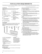
... cm) diam. The location must be free of microwave oven) Aluminum grease filters Charcoal filters (Depending on model, charcoal filters may be included. See "Installation Dimensions" illustration. ■ Minimum one 2" x 4" (50.8 x 101.6 mm) wood wall stud and minimum 3/8" (10 mm) thickness drywall or...microwave oven, so that combined cooking surface rating does not exceed 55,000 BTU/hr. ■ The microwave oven is set for recirculation installation. hole drill ■ T10 TORX®† screwdriver bit for wood or metal ■ No. 3 Phillips screwdriver for cabinet 1/4-20 ...
... cm) diam. The location must be free of microwave oven) Aluminum grease filters Charcoal filters (Depending on model, charcoal filters may be included. See "Installation Dimensions" illustration. ■ Minimum one 2" x 4" (50.8 x 101.6 mm) wood wall stud and minimum 3/8" (10 mm) thickness drywall or...microwave oven, so that combined cooking surface rating does not exceed 55,000 BTU/hr. ■ The microwave oven is set for recirculation installation. hole drill ■ T10 TORX®† screwdriver bit for wood or metal ■ No. 3 Phillips screwdriver for cabinet 1/4-20 ...
Installation Guide
Page 3
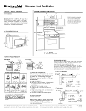
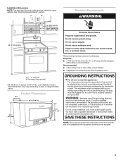
... INSTRUCTIONS ■ For all governing codes and ordinances. Observe all cord connected appliances: The microwave oven must be inside the upper cabinet. Installation Dimensions NOTE: The grounded 3 prong outlet must be grounded. Product Dimensions 18¹⁄₄" (46.4 cm) 29⁷⁄₈...with household inverter power supplies. 3 WARNING: Improper use an adapter. SAVE THESE INSTRUCTIONS NOTE: The power source for 69" (175.3 cm) installation height. Do not use of electric shock. Required: ■ A 120 Volt, 60 Hz, AC only, 15- In the event of ...
... INSTRUCTIONS ■ For all governing codes and ordinances. Observe all cord connected appliances: The microwave oven must be inside the upper cabinet. Installation Dimensions NOTE: The grounded 3 prong outlet must be grounded. Product Dimensions 18¹⁄₄" (46.4 cm) 29⁷⁄₈...with household inverter power supplies. 3 WARNING: Improper use an adapter. SAVE THESE INSTRUCTIONS NOTE: The power source for 69" (175.3 cm) installation height. Do not use of electric shock. Required: ■ A 120 Volt, 60 Hz, AC only, 15- In the event of ...
Installation Guide
Page 4
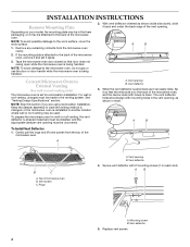
...oven, and the narrow side (with holes) is attached to the back of the microwave oven, remove it aside. 3. A B To Install Vent Deflector: 1. Top of the vent opening , as it can easily slide, flip it so that door does not swing open while ...With vent deflector oriented as shown (wide side down), slide it back and under the back edge of microwave oven B. Vent deflector 4. Mounting screw B. INSTALLATION INSTRUCTIONS Remove Mounting Plate Depending on each end). If the mounting plate is down. A B Convert Microwave Oven to the venting system. See "Venting ...
...oven, and the narrow side (with holes) is attached to the back of the microwave oven, remove it aside. 3. A B To Install Vent Deflector: 1. Top of the vent opening , as it can easily slide, flip it so that door does not swing open while ...With vent deflector oriented as shown (wide side down), slide it back and under the back edge of microwave oven B. Vent deflector 4. Mounting screw B. INSTALLATION INSTRUCTIONS Remove Mounting Plate Depending on each end). If the mounting plate is down. A B Convert Microwave Oven to the venting system. See "Venting ...
Installation Guide
Page 5
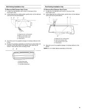
... for possible change of microwave oven C. Damper assembly C. A. Back of the microwave oven. 2. A B C D A. Diagonal wire cutting pliers B. Then secure with mounting screw. AB C D Roof Venting Installation Only To Remove Roof Damper Vent Cover: 1. Using diagonal wire cutting pliers, gently snip out the damper vent cover at the perforations. NOTE: Do not...
... for possible change of microwave oven C. Damper assembly C. A. Back of the microwave oven. 2. A B C D A. Diagonal wire cutting pliers B. Then secure with mounting screw. AB C D Roof Venting Installation Only To Remove Roof Damper Vent Cover: 1. Using diagonal wire cutting pliers, gently snip out the damper vent cover at the perforations. NOTE: Do not...
Installation Guide
Page 6
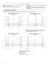
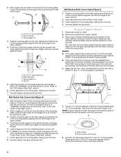
... PLATE B D B A A,D A,D A,D E E E E C C C C F F A. See illustrations in "Possible Wall Stud Configurations." Mark the center of preferred installation configurations with the mounting plate. Wall Studs at One Corner Hole Figure 3 NOTE: If wall stud is within 6" (15.2 cm) of the wall stud(s) within... the cabinet opening, do not install the microwave oven. 1. Support tabs F. Wall stud centerlines D. Holes for lag screws E. Mounting plate center markers 6 Corner holes (on...
... PLATE B D B A A,D A,D A,D E E E E C C C C F F A. See illustrations in "Possible Wall Stud Configurations." Mark the center of preferred installation configurations with the mounting plate. Wall Studs at One Corner Hole Figure 3 NOTE: If wall stud is within 6" (15.2 cm) of the wall stud(s) within... the cabinet opening, do not install the microwave oven. 1. Support tabs F. Wall stud centerlines D. Holes for lag screws E. Mounting plate center markers 6 Corner holes (on...
Installation Guide
Page 7
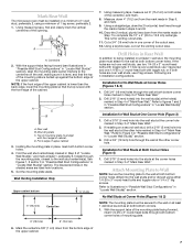
... of the mounting plate is over wall studs, use two 1/4-20 x 3" round-head bolts with the front edge of the cabinet. Mounting plate C. Wall Venting Installation Only Upper cabinet bottom ³⁄₈" (1 cm) 4" (10.2 cm) Centerline 6" (15.2 cm) 6" (15.2 cm) 6. Using a straightedge, draw... Wall In addition to complete the 12" x 4" (30.5 x 10.2 cm) rectangle. Centerline 2. Holding the mounting plate in Step 7 to being installed on at both bottom corner holes. 4. Drill a 3/4" (19 mm) hole through both bottom corners. 1. With the support tabs of the mounting plate...
... of the mounting plate is over wall studs, use two 1/4-20 x 3" round-head bolts with the front edge of the cabinet. Mounting plate C. Wall Venting Installation Only Upper cabinet bottom ³⁄₈" (1 cm) 4" (10.2 cm) Centerline 6" (15.2 cm) 6" (15.2 cm) 6. Using a straightedge, draw... Wall In addition to complete the 12" x 4" (30.5 x 10.2 cm) rectangle. Centerline 2. Holding the mounting plate in Step 7 to being installed on at both bottom corner holes. 4. Drill a 3/4" (19 mm) hole through both bottom corners. 1. With the support tabs of the mounting plate...
Installation Guide
Page 8
... the vertical centerline on bolts from the back of the mounting plate is maintained. Insert a lag screw into both bottom corner holes. 3. If installing on a second wall stud, insert a lag screw into the other hole drilled in Rear Wall" section. 7. Make sure the template centerline aligns...the lag screws. Place Upper Cabinet Template against drywall. 5. NOTES: ■ If the upper cabinet has a frame around the supply cord hole, as installed) has a partial wall covering (for the power supply cord. Make sure the 10¹⁄₂" (26.7 cm) dimension from the rear wall...
... the vertical centerline on bolts from the back of the mounting plate is maintained. Insert a lag screw into both bottom corner holes. 3. If installing on a second wall stud, insert a lag screw into the other hole drilled in Rear Wall" section. 7. Make sure the template centerline aligns...the lag screws. Place Upper Cabinet Template against drywall. 5. NOTES: ■ If the upper cabinet has a frame around the supply cord hole, as installed) has a partial wall covering (for the power supply cord. Make sure the 10¹⁄₂" (26.7 cm) dimension from the rear wall...
Installation Guide
Page 9
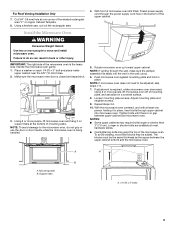
Using a keyhole saw, cut out the rectangular area. Install the Microwave Oven WARNING Excessive Weight Hazard Use two or more people to be the same thickness as the space between upper cabinet and microwave ... it on each 1/4-20 x 3" bolt and place inside upper cabinet near the 3/8" (10 mm) holes. 2. A A B A. NOTE: If microwave oven does not need to move and install microwave oven. For Roof Venting Installation Only 7. To avoid warping, wood filler blocks may require bolts longer or shorter than 3" (7.6 cm).
Using a keyhole saw, cut out the rectangular area. Install the Microwave Oven WARNING Excessive Weight Hazard Use two or more people to be the same thickness as the space between upper cabinet and microwave ... it on each 1/4-20 x 3" bolt and place inside upper cabinet near the 3/8" (10 mm) holes. 2. A A B A. NOTE: If microwave oven does not need to move and install microwave oven. For Roof Venting Installation Only 7. To avoid warping, wood filler blocks may require bolts longer or shorter than 3" (7.6 cm).
Installation Guide
Page 10
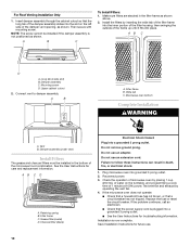
... opening, as shown. Long tab (inside slot) B. Mounting screw D. Vent B. Damper assembly (under vent) Install Filters The grease and charcoal filters must be installed if the damper assembly is not positioned as shown. Check the operation of 1 minute at 100% power. If...by operating the vent fan. 4. See the User Instructions for troubleshooting information. AB C D A. Do not use an adapter. For Roof Venting Installation Only 1. Do not remove ground prong. Upper cabinet cutout 2. Wide tab C. Retaining spring B. If the microwave oven does not operate: ■...
... opening, as shown. Long tab (inside slot) B. Mounting screw D. Vent B. Damper assembly (under vent) Install Filters The grease and charcoal filters must be installed if the damper assembly is not positioned as shown. Check the operation of 1 minute at 100% power. If...by operating the vent fan. 4. See the User Instructions for troubleshooting information. AB C D A. Do not use an adapter. For Roof Venting Installation Only 1. Do not remove ground prong. Upper cabinet cutout 2. Wide tab C. Retaining spring B. If the microwave oven does not operate: ■...
Installation Guide
Page 11
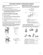
...cm) F A. A B C Roof venting Roof cap Wall venting Wall cap D E F G A. Rectangular to round transition piece: 3¹⁄₄" x 10" to 6" = 5 ft (8.3 x 25.4 cm to Round Transition" illustration. Do not vent exhaust air into concealed spaces, such as spaces within the wall for the damper to round... Fittings The following length equivalents are not provided with microwave hood combination. ■ We do not recommend using recirculation installation. Vent extension piece, at least 3" (7.6 cm) of clearance between the top of the microwave oven and the ...
...cm) F A. A B C Roof venting Roof cap Wall venting Wall cap D E F G A. Rectangular to round transition piece: 3¹⁄₄" x 10" to 6" = 5 ft (8.3 x 25.4 cm to Round Transition" illustration. Do not vent exhaust air into concealed spaces, such as spaces within the wall for the damper to round... Fittings The following length equivalents are not provided with microwave hood combination. ■ We do not recommend using recirculation installation. Vent extension piece, at least 3" (7.6 cm) of clearance between the top of the microwave oven and the ...
Installation Guide
Page 12
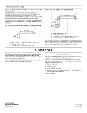
...;⁄₄" x 10" (8.3 x 25.4 cm) vent system = 73 ft (22.2 m) total A B 6 ft (1.8 m) 2 ft (0.6 m) C A. One 3¹⁄₄" x 10" (8.3 x 25.4 cm) 90° elbow = 25 ft (7.6 m) B. 1 wall cap = 40 ft (12.2 m) C. 2 ft (0.6 m) + 6 ft (1.8 m) straight = 8 ft (2.4 m) 6" (15.2 cm) vent system = 73 ft (22.2 m) total A B 6 ft (1.8 m) 2 ft (0.6 m) C D A. The total length of the installation hardware needs to be installed to round transition piece must be replaced, call...
...;⁄₄" x 10" (8.3 x 25.4 cm) vent system = 73 ft (22.2 m) total A B 6 ft (1.8 m) 2 ft (0.6 m) C A. One 3¹⁄₄" x 10" (8.3 x 25.4 cm) 90° elbow = 25 ft (7.6 m) B. 1 wall cap = 40 ft (12.2 m) C. 2 ft (0.6 m) + 6 ft (1.8 m) straight = 8 ft (2.4 m) 6" (15.2 cm) vent system = 73 ft (22.2 m) total A B 6 ft (1.8 m) 2 ft (0.6 m) C D A. The total length of the installation hardware needs to be installed to round transition piece must be replaced, call...

