Installation Instructions
Page 1
Installation Instructions 30" (76.2 cm) and 36" (91.4 cm) ELECTRIC Built-in Ceramic Downdraft Cooktop IMPORTANT: Read and save these instructions. Save Installation Instructions for future reference. Both numbers are on the model/serial rating plate, located on the bottom of the cooktop. Model Serial Part No. 8286553 Homeowner: Keep Installation Instructions for local electrical inspector's use. IMPORTANT: Installer: Leave Installation Instructions with the homeowner. Write down the model and serial numbers before installing cooktop.
Installation Instructions 30" (76.2 cm) and 36" (91.4 cm) ELECTRIC Built-in Ceramic Downdraft Cooktop IMPORTANT: Read and save these instructions. Save Installation Instructions for future reference. Both numbers are on the model/serial rating plate, located on the bottom of the cooktop. Model Serial Part No. 8286553 Homeowner: Keep Installation Instructions for local electrical inspector's use. IMPORTANT: Installer: Leave Installation Instructions with the homeowner. Write down the model and serial numbers before installing cooktop.
Installation Instructions
Page 2
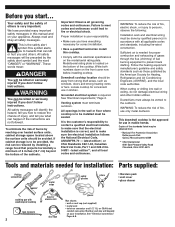
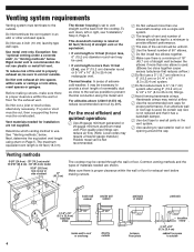
... caulking tape measure 2 hand or electric drill duct tape gloves Not shown: • wall or roof cap (not supplied) • metal vent • twist-on the model/serial rating plate. Locate cooktop for proper combustion and exhausting of gases through the flue (chimney) of the cabinets. All openings in kitchen. or CSA-listed conduit connector. WARNING You can happen if the instructions are not followed. Proper installation...
... caulking tape measure 2 hand or electric drill duct tape gloves Not shown: • wall or roof cap (not supplied) • metal vent • twist-on the model/serial rating plate. Locate cooktop for proper combustion and exhausting of gases through the flue (chimney) of the cabinets. All openings in kitchen. or CSA-listed conduit connector. WARNING You can happen if the instructions are not followed. Proper installation...
Installation Instructions
Page 3
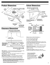
... provide required 0" (0 cm) clearance. Replacement installation - Rear clearance - 3/4" (19.1 mm) clearance between motor and cabinet is required for proper cooling. 6" (15.2 cm) clearance is recommended for minimum clearances Minimum distance to nearest combustible vertical surface extending 18" (45.7 cm) above cooktop 1" (25.4 mm) Do Not seal cooktop to countertop. 21" (53.3 cm) opening dimensions that front edge of cutout. countertop Install rear wall junction box in shaded area. Cut radius corners and file to smooth...
... provide required 0" (0 cm) clearance. Replacement installation - Rear clearance - 3/4" (19.1 mm) clearance between motor and cabinet is required for proper cooling. 6" (15.2 cm) clearance is recommended for minimum clearances Minimum distance to nearest combustible vertical surface extending 18" (45.7 cm) above cooktop 1" (25.4 mm) Do Not seal cooktop to countertop. 21" (53.3 cm) opening dimensions that front edge of cutout. countertop Install rear wall junction box in shaded area. Cut radius corners and file to smooth...
Installation Instructions
Page 4
... cutouts. Rigid metal vent is proper clearance within walls or ceilings or into a single vent system. ࠜ The length of vent and number of elbows should be kept to a minimum to provide efficient performance. ࠜ The size of the vent should be used. • If vent length is a minimum of 18" (45.7 cm) of materials needed for the exhaust vent. See "Venting methods," below . This downdraft cooktop is rated...
... cutouts. Rigid metal vent is proper clearance within walls or ceilings or into a single vent system. ࠜ The length of vent and number of elbows should be kept to a minimum to provide efficient performance. ࠜ The size of the vent should be used. • If vent length is a minimum of 18" (45.7 cm) of materials needed for the exhaust vent. See "Venting methods," below . This downdraft cooktop is rated...
Installation Instructions
Page 5
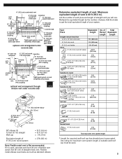
..." (8.3 x 25.4 cm) air flow wall cap* 3-1/4" x 10" (8.3 x 25.4 cm) 5 ft. (1.5 m) 1 ft. (30.5 cm) 0 ft. (0 cm) 6" (15.2 cm) round roof cap* 10" x 10" (25.4 X 25.4 cm) thermal break 6" (15.2 cm) round 0 ft. (0 cm) 0 ft. (0 cm) 2 ft. (61 cm) Total equivalent vent system length * Length for required wall/roof cap has already been incorporated into rating for maximum vent system length. If...
..." (8.3 x 25.4 cm) air flow wall cap* 3-1/4" x 10" (8.3 x 25.4 cm) 5 ft. (1.5 m) 1 ft. (30.5 cm) 0 ft. (0 cm) 6" (15.2 cm) round roof cap* 10" x 10" (25.4 X 25.4 cm) thermal break 6" (15.2 cm) round 0 ft. (0 cm) 0 ft. (0 cm) 2 ft. (61 cm) Total equivalent vent system length * Length for required wall/roof cap has already been incorporated into rating for maximum vent system length. If...
Installation Instructions
Page 6
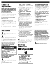
... "Electrical connections," Pages 6-8. The fuse size must be connected to a grounded, metallic permanent wiring system or a ground connector should connect cooktop directly to allow as much slack as specified on the model/serial rating plate. ࠜ CONNECT WITH COPPER WIRE ONLY. ࠜ Connected directly to the fused disconnect (or circuit breaker box) through flexible, armored or nonmetallic sheathed, copper cable (with a wall or roof cap outside the building. See "Venting requirements," Pages 4-5. or CSA-listed...
... "Electrical connections," Pages 6-8. The fuse size must be connected to a grounded, metallic permanent wiring system or a ground connector should connect cooktop directly to allow as much slack as specified on the model/serial rating plate. ࠜ CONNECT WITH COPPER WIRE ONLY. ࠜ Connected directly to the fused disconnect (or circuit breaker box) through flexible, armored or nonmetallic sheathed, copper cable (with a wall or roof cap outside the building. See "Venting requirements," Pages 4-5. or CSA-listed...
Installation Instructions
Page 7
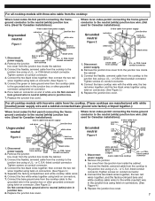
... C.S.A.-listed conduit connector. Replace the junction box cover. 7 Remove the junction bare or green wires 3-wire cable from cooktop power supply. or CSA- then connect the two red wires together using twist-on conduit connector. 4. Separate the factory-crimped bare and white cooktop cable wires. 6. Disconnect 4-wire cable from cooktop black wires U.L.- For all cooktop models with four-wire cable from the cooktop. (These cooktops are manufactured with white [neutral] power supply wire and a cabinet-connected bare ground wire...
... C.S.A.-listed conduit connector. Replace the junction box cover. 7 Remove the junction bare or green wires 3-wire cable from cooktop power supply. or CSA- then connect the two red wires together using twist-on conduit connector. 4. Separate the factory-crimped bare and white cooktop cable wires. 6. Disconnect 4-wire cable from cooktop black wires U.L.- For all cooktop models with four-wire cable from the cooktop. (These cooktops are manufactured with white [neutral] power supply wire and a cabinet-connected bare ground wire...
Installation Instructions
Page 8
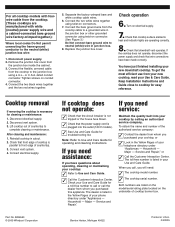
... not operate, disconnect the power supply and check that wire connections have just finished installing your new downdraft cooktop. Cooktop removal If removing the cooktop is necessary for easy reference. Disconnect electrical supply. 2. Check your Use and Care Guide for a toll-free number to neutral (white) wire in junction box. 8. Household - If you need service: Maintain the quality built into the outlet (120 V models). ✓ See Use and Care Guide for operating and cleaning instructions. When you call...
... not operate, disconnect the power supply and check that wire connections have just finished installing your new downdraft cooktop. Cooktop removal If removing the cooktop is necessary for easy reference. Disconnect electrical supply. 2. Check your Use and Care Guide for a toll-free number to neutral (white) wire in junction box. 8. Household - If you need service: Maintain the quality built into the outlet (120 V models). ✓ See Use and Care Guide for operating and cleaning instructions. When you call...
Use and Care Guide
Page 2
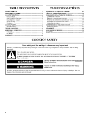
... will tell you what the potential hazard is the safety alert symbol. All safety messages will follow instructions. TABLE OF CONTENTS COOKTOP SAFETY 2 PARTS AND FEATURES 4 COOKTOP CONTROLS 6 Knob Controls 6 Dual/Triple-Size Elements 6 Downdraft Vent System 7 Home Canning 7 Cookware 7 COOKTOP CARE 8 General Cleaning 8 TROUBLESHOOTING 8 ASSISTANCE OR SERVICE 9 In the U.S.A 9 In Canada 9 WARRANTY 10 TABLE DES MATIÈRES SÉCURITÉ DE LA TABLE DE CUISSON 11 PI...
... will tell you what the potential hazard is the safety alert symbol. All safety messages will follow instructions. TABLE OF CONTENTS COOKTOP SAFETY 2 PARTS AND FEATURES 4 COOKTOP CONTROLS 6 Knob Controls 6 Dual/Triple-Size Elements 6 Downdraft Vent System 7 Home Canning 7 Cookware 7 COOKTOP CARE 8 General Cleaning 8 TROUBLESHOOTING 8 ASSISTANCE OR SERVICE 9 In the U.S.A 9 In Canada 9 WARRANTY 10 TABLE DES MATIÈRES SÉCURITÉ DE LA TABLE DE CUISSON 11 PI...
Use and Care Guide
Page 3
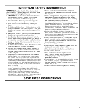
... Use Water on Cooktop - Smother fire or flame or use aluminum foil to sit or stand on a hot cooking area, be left alone or unattended in the manual. Do not let potholder touch hot heating elements. s Never Leave Surface Units Unattended at High Heat Settings - If a wet sponge or cloth is used to wipe spills on any part of clothing. SAVE THESE INSTRUCTIONS 3 s Do Not Leave Children Alone - s User Servicing...
... Use Water on Cooktop - Smother fire or flame or use aluminum foil to sit or stand on a hot cooking area, be left alone or unattended in the manual. Do not let potholder touch hot heating elements. s Never Leave Surface Units Unattended at High Heat Settings - If a wet sponge or cloth is used to wipe spills on any part of clothing. SAVE THESE INSTRUCTIONS 3 s Do Not Leave Children Alone - s User Servicing...
Use and Care Guide
Page 4
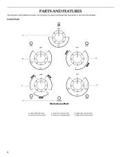
Downdraft fan knob B. Left rear control knob C. Right rear control knob F. Right front control knob 4 The cooktop you have purchased may have some or all of the items listed. Control Panel A B E C F D A. Left front control knob D. Power on indicator light E. PARTS AND FEATURES This manual covers different models.
Downdraft fan knob B. Left rear control knob C. Right rear control knob F. Right front control knob 4 The cooktop you have purchased may have some or all of the items listed. Control Panel A B E C F D A. Left front control knob D. Power on indicator light E. PARTS AND FEATURES This manual covers different models.

Use and Care Guide
Page 5
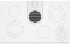
Surface cooking area F. Power on outside bottom of cooktop) G G. Model and serial number plate (located on indicator light H. Control panel I D E H A. Cooktop A B C I . Ceramic glass cooktop F D. Stainless steel frame (on some models) 5 Downdraft vent cover B. Downdraft vent location E. Filter C.
Surface cooking area F. Power on outside bottom of cooktop) G G. Model and serial number plate (located on indicator light H. Control panel I D E H A. Cooktop A B C I . Ceramic glass cooktop F D. Stainless steel frame (on some models) 5 Downdraft vent cover B. Downdraft vent location E. Filter C.
Use and Care Guide
Page 6
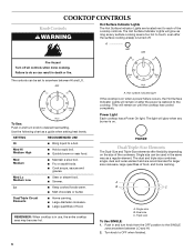
... cookware. Failure to desired heat setting. Dual/Triple Circuit Elements s Home canning. Power Light Each cooktop has a Power On light. Push in and turn knob to do so can result in use, the entire cooktop area may become hot. 6 A. Dual size C. Dual/Triple-Size Elements The Dual-Size and Triple-Size elements offer flexibility depending on when a power failure occurs, the Hot Surface Indicator Lights will glow as long as a guide when setting heat levels. The dual and...
... cookware. Failure to desired heat setting. Dual/Triple Circuit Elements s Home canning. Power Light Each cooktop has a Power On light. Push in and turn knob to do so can result in use, the entire cooktop area may become hot. 6 A. Dual size C. Dual/Triple-Size Elements The Dual-Size and Triple-Size elements offer flexibility depending on when a power failure occurs, the Hot Surface Indicator Lights will glow as long as a guide when setting heat levels. The dual and...
Use and Care Guide
Page 7
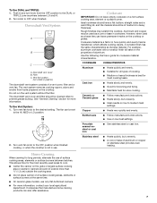
... types of a vent cover, filter and a vent fan. s Ideal results on the cooktop or grates. s A core or base of aluminum. To Use Vent System: 1. Turn vent fan knob to the OFF position when finished cooking, or when the cooktop is best for cookware material characteristics. s Do not place canner on the properties of aluminum or copper on a hot surface cooking area, element or surface burner. For example, aluminum cookware with a nonstick finish will take on 2 surface cooking areas, elements...
... types of a vent cover, filter and a vent fan. s Ideal results on the cooktop or grates. s A core or base of aluminum. To Use Vent System: 1. Turn vent fan knob to the OFF position when finished cooking, or when the cooktop is best for cookware material characteristics. s Do not place canner on the properties of aluminum or copper on a hot surface cooking area, element or surface burner. For example, aluminum cookware with a nonstick finish will take on 2 surface cooking areas, elements...
Use and Care Guide
Page 8
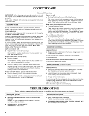
... order. Replace the fuse or reset the circuit breaker. Push in knob before turning to avoid damaging. COOKTOP CONTROLS Cleaning Method: s Soap and water or dishwasher: Pull knobs straight away from aluminum and copper s Cooktop Polishing Creme: Clean as soon as possible on cleaning products. Continue rubbing until white film disappears. COOKTOP CARE General Cleaning IMPORTANT: Before cleaning, make sure knobs are in the Off position. Always follow label instructions on surface and scrape...
... order. Replace the fuse or reset the circuit breaker. Push in knob before turning to avoid damaging. COOKTOP CONTROLS Cleaning Method: s Soap and water or dishwasher: Pull knobs straight away from aluminum and copper s Cooktop Polishing Creme: Clean as soon as possible on cleaning products. Continue rubbing until white film disappears. COOKTOP CARE General Cleaning IMPORTANT: Before cleaning, make sure knobs are in the Off position. Always follow label instructions on surface and scrape...
Use and Care Guide
Page 9
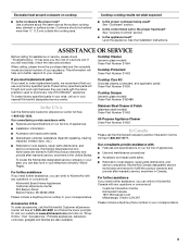
... "Troubleshooting." Or visit our website at 1-800-442-9991 and follow the instructions below. Cooktop Care Kit (includes cleaner, protectant, and applicator pads) Order Part Number 31605 Cooktop Scraper (ceramic glass models) Order Part Number 3183488 In the U.S.A. s Referrals to fulfill the product warranty and provide after -warranty service, anywhere in your appliance. Stainless Steel Cleaner & Polish (stainless steel models) Order Part Number 31462 All-Purpose Appliance Cleaner Order Part Number 31662 In Canada Please call . KitchenAid...
... "Troubleshooting." Or visit our website at 1-800-442-9991 and follow the instructions below. Cooktop Care Kit (includes cleaner, protectant, and applicator pads) Order Part Number 31605 Cooktop Scraper (ceramic glass models) Order Part Number 3183488 In the U.S.A. s Referrals to fulfill the product warranty and provide after -warranty service, anywhere in your appliance. Stainless Steel Cleaner & Polish (stainless steel models) Order Part Number 31462 All-Purpose Appliance Cleaner Order Part Number 31662 In Canada Please call . KitchenAid...
Use and Care Guide
Page 10
... model number and serial number. Service calls to repair or replace appliance light bulbs, air filters or water filters. In the U.S.A., call 1-800-807-6777. 9/07 Keep this book and your sales slip together for product service if your major appliance is located in which it is installed in an inaccessible location or is not installed in materials or workmanship: ■ Electric element ■ Gas burners ■ Solid state touch control...
... model number and serial number. Service calls to repair or replace appliance light bulbs, air filters or water filters. In the U.S.A., call 1-800-807-6777. 9/07 Keep this book and your sales slip together for product service if your major appliance is located in which it is installed in an inaccessible location or is not installed in materials or workmanship: ■ Electric element ■ Gas burners ■ Solid state touch control...

Parts List
Page 2
... Cashmere Metalic 21 3192530 Filter, Grease 25 9759094 Spring, Locator 486754 Screw 30 3193032 Gasket, Vent Shield 33 8286055 Light, Hot Surface Indicator 35 3193094 Plate, Cover 2 8186306 Part No. No. Part No. DESCRIPTION 1 Literature Parts 7 8285810 Box, Burner 8286553 Installation 8 3183956 Seal, Switch Cover Instructions 9 8285934 Shield, Vent 8286428 Wiring Diagram 3177991 Screw 8286080 Use & Care Guide 10 3190656 Drip Bowl, Grease 3191638 Safe Cooking Tips 11 4455354 Bracket, Mounting 9759133 Safe Cooking Tips Control 2 Cooktop, Glass & 12 311865 Screw...
... Cashmere Metalic 21 3192530 Filter, Grease 25 9759094 Spring, Locator 486754 Screw 30 3193032 Gasket, Vent Shield 33 8286055 Light, Hot Surface Indicator 35 3193094 Plate, Cover 2 8186306 Part No. No. Part No. DESCRIPTION 1 Literature Parts 7 8285810 Box, Burner 8286553 Installation 8 3183956 Seal, Switch Cover Instructions 9 8285934 Shield, Vent 8286428 Wiring Diagram 3177991 Screw 8286080 Use & Care Guide 10 3190656 Drip Bowl, Grease 3191638 Safe Cooking Tips 11 4455354 Bracket, Mounting 9759133 Safe Cooking Tips Control 2 Cooktop, Glass & 12 311865 Screw...
Parts List
Page 3
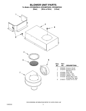
Part No. DESCRIPTION 1 8285958 Bracket, Shield 2 3192403 Bracket, Blower Mounting 4 9760484 Ring, Inlet 5 9760485 Screen, Inlet 6 9760483 Adapter, Vent 7 9760440 Blower Motor Asm. (Includes Fan Asm) 8 3196537 Screw, 8−18 x 3/8 3 BLOWER UNIT PARTS For Models: KECD866RBL00, KECD866RWW00, KECD866RSS00 (Black) (White on White) (S.Steel) 8186306 Illus. No.
Part No. DESCRIPTION 1 8285958 Bracket, Shield 2 3192403 Bracket, Blower Mounting 4 9760484 Ring, Inlet 5 9760485 Screen, Inlet 6 9760483 Adapter, Vent 7 9760440 Blower Motor Asm. (Includes Fan Asm) 8 3196537 Screw, 8−18 x 3/8 3 BLOWER UNIT PARTS For Models: KECD866RBL00, KECD866RWW00, KECD866RSS00 (Black) (White on White) (S.Steel) 8186306 Illus. No.
Parts List
Page 4
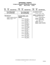
... Ga. 150 C 242829 Wire, Red 12 Ga. 150 C 242825 Wire, Red 14 Ga. 150 C 242831 Wire, Red 14 Ga. 200 C 242826 Wire, White 14 Ga. 150 C 242827 Wire, Yellow 14 Ga. 150 C 242832 Wire, Yellow 14 Ga. 200 C Illus. Part No. DESCRIPTION FOLLOWING PARTS NOT ILLUSTRATED FOLLOWING PARTS NOT ILLUSTRATED Miscellaneous 3172515 Hardware, Mounting 4455917 Bracket, Support 3400093 Screw SPLICING WIRES−−25FT. OPTIONAL PARTS For Models: KECD866RBL00, KECD866RWW00, KECD866RSS00 (Black) (White on White) (S.Steel...
... Ga. 150 C 242829 Wire, Red 12 Ga. 150 C 242825 Wire, Red 14 Ga. 150 C 242831 Wire, Red 14 Ga. 200 C 242826 Wire, White 14 Ga. 150 C 242827 Wire, Yellow 14 Ga. 150 C 242832 Wire, Yellow 14 Ga. 200 C Illus. Part No. DESCRIPTION FOLLOWING PARTS NOT ILLUSTRATED FOLLOWING PARTS NOT ILLUSTRATED Miscellaneous 3172515 Hardware, Mounting 4455917 Bracket, Support 3400093 Screw SPLICING WIRES−−25FT. OPTIONAL PARTS For Models: KECD866RBL00, KECD866RWW00, KECD866RSS00 (Black) (White on White) (S.Steel...


