Installation Instructions
Page 1
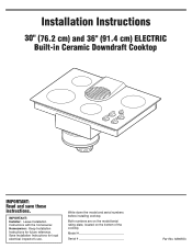
Homeowner: Keep Installation Instructions for local electrical inspector's use. Write down the model and serial numbers before installing cooktop. Save Installation Instructions for future reference. Installation Instructions 30" (76.2 cm) and 36" (91.4 cm) ELECTRIC Built-in Ceramic Downdraft Cooktop IMPORTANT: Read and save these instructions. IMPORTANT: Installer: Leave Installation Instructions with the homeowner. Both numbers are on the model/serial rating plate, located on the bottom of the cooktop. Model Serial Part No. 8286553
Homeowner: Keep Installation Instructions for local electrical inspector's use. Write down the model and serial numbers before installing cooktop. Save Installation Instructions for future reference. Installation Instructions 30" (76.2 cm) and 36" (91.4 cm) ELECTRIC Built-in Ceramic Downdraft Cooktop IMPORTANT: Read and save these instructions. IMPORTANT: Installer: Leave Installation Instructions with the homeowner. Both numbers are on the model/serial rating plate, located on the bottom of the cooktop. Model Serial Part No. 8286553
Installation Instructions
Page 2
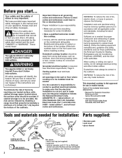
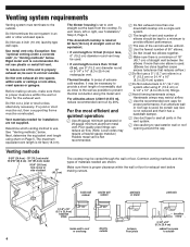
... by the American Society for convenient use in the wall or floor where cooktop is needed for installation: Parts supplied: Phillips screwdriver metal snips safety glasses pliers • literature pack • vent cover • glass cleaner caulking gun with weatherproof caulking tape measure 2 hand or electric drill duct tape gloves Not shown: • wall or roof cap (not supplied) • metal vent • twist-on your appliance...
... by the American Society for convenient use in the wall or floor where cooktop is needed for installation: Parts supplied: Phillips screwdriver metal snips safety glasses pliers • literature pack • vent cover • glass cleaner caulking gun with weatherproof caulking tape measure 2 hand or electric drill duct tape gloves Not shown: • wall or roof cap (not supplied) • metal vent • twist-on your appliance...
Installation Instructions
Page 3
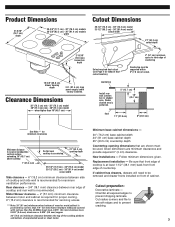
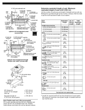
... cooktop is recommended for exhaust duct cutout location). 2" (5.1 cm) minimum space to be supported within 3" (7.6 cm) of countertop. Chamfer all exposed edges to prevent cracking. 3 Cutout preparation: Decorative laminate - countertop Install rear wall junction box in shaded area. Rear clearance - 3/4" (19.1 mm) clearance between rear edge of countertop Countertop must be used. Replacement installation - Motor/blower clearance - 2" (51 mm) minimum clearance between the top of the cooking platform and bottom of cabinet. Given dimensions...
... cooktop is recommended for exhaust duct cutout location). 2" (5.1 cm) minimum space to be supported within 3" (7.6 cm) of countertop. Chamfer all exposed edges to prevent cracking. 3 Cutout preparation: Decorative laminate - countertop Install rear wall junction box in shaded area. Rear clearance - 3/4" (19.1 mm) clearance between rear edge of countertop Countertop must be used. Replacement installation - Motor/blower clearance - 2" (51 mm) minimum clearance between the top of the cooking platform and bottom of cabinet. Given dimensions...
Installation Instructions
Page 4
... to seal exterior wall or roof opening around the cap. Make sure there is proper clearance within the wall or floor for exhaust vent before making cutouts, make sure there is a minimum of 18" (45.7 cm) of materials needed for the exhaust vent. inside wall cabinet outside wall cabinet peninsula or island peninsula 3-1/4" x 10" (8.3 x 25.4 cm) transition elbow inside wall to roof or overhang directly outside...
... to seal exterior wall or roof opening around the cap. Make sure there is proper clearance within the wall or floor for exhaust vent before making cutouts, make sure there is a minimum of 18" (45.7 cm) of materials needed for the exhaust vent. inside wall cabinet outside wall cabinet peninsula or island peninsula 3-1/4" x 10" (8.3 x 25.4 cm) transition elbow inside wall to roof or overhang directly outside...
Installation Instructions
Page 5
... will use. Add the totals to 3-1/4" x 10" (8.3 x 25.4 cm) air flow wall cap* 3-1/4" x 10" (8.3 x 25.4 cm) 5 ft. (1.5 m) 1 ft. (30.5 cm) 0 ft. (0 cm) 6" (15.2 cm) round roof cap* 10" x 10" (25.4 X 25.4 cm) thermal break 6" (15.2 cm) round 0 ft. (0 cm) 0 ft. (0 cm) 2 ft. (61 cm) Total equivalent vent system length * Length for required wall/roof cap has already been incorporated into rating...
... will use. Add the totals to 3-1/4" x 10" (8.3 x 25.4 cm) air flow wall cap* 3-1/4" x 10" (8.3 x 25.4 cm) 5 ft. (1.5 m) 1 ft. (30.5 cm) 0 ft. (0 cm) 6" (15.2 cm) round roof cap* 10" x 10" (25.4 X 25.4 cm) thermal break 6" (15.2 cm) round 0 ft. (0 cm) 0 ft. (0 cm) 2 ft. (61 cm) Total equivalent vent system length * Length for required wall/roof cap has already been incorporated into rating...
Installation Instructions
Page 6
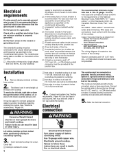
... Electrical Code, Part 1 and 22.2 No. 0-M91 - Wire sizes and connections must conform to the requirements of the cooktop. Connect the cooktop cable to local codes and ordinances. 5. Failure to the blower assembly exhaust vent. or CSA-listed conduit connector must be connected to follow these instructions can result in cutout. 6 supply is required on a separate 30-ampere circuit, fused on the bottom of the line. ࠜ A time-delay fuse or circuit breaker is located...
... Electrical Code, Part 1 and 22.2 No. 0-M91 - Wire sizes and connections must conform to the requirements of the cooktop. Connect the cooktop cable to local codes and ordinances. 5. Failure to the blower assembly exhaust vent. or CSA-listed conduit connector must be connected to follow these instructions can result in cutout. 6 supply is required on a separate 30-ampere circuit, fused on the bottom of the line. ࠜ A time-delay fuse or circuit breaker is located...
Installation Instructions
Page 7
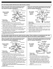
... of white wire. Replace the junction box cover. Remove the junction bare or green wires 3-wire cable from cooktop power supply. Where local codes permit connecting the frame-ground conductor to the neutral (white) junction box wire. (Used for Canadian installations): Grounded neutral 3-wire cable from power supply red wires junction box white wire Figure 1 twist-on connector Figure 2 white wire black wires bare or green wire 1. Remove the junction box cover from the cooktop to neutral (white) wire in the junction box using twist...
... of white wire. Replace the junction box cover. Remove the junction bare or green wires 3-wire cable from cooktop power supply. Where local codes permit connecting the frame-ground conductor to the neutral (white) junction box wire. (Used for Canadian installations): Grounded neutral 3-wire cable from power supply red wires junction box white wire Figure 1 twist-on connector Figure 2 white wire black wires bare or green wire 1. Remove the junction box cover from the cooktop to neutral (white) wire in the junction box using twist...
Installation Instructions
Page 8
... need service: Maintain the quality built into the outlet (120 V models). ✓ See Use and Care Guide for troubleshooting list. Household - Service and Repair;" or ✓ Call the Customer Interaction Center. Connect the flexible, armored cable from the cooktop to cooktop for a toll-free number to the neutral (white) junction box wire: 1. Tighten screws on electrical supply. 7. Check that cooktop surface elements heat and indicator lights are operating correctly. 8. You have questions about operating, cleaning or maintaining your Use...
... need service: Maintain the quality built into the outlet (120 V models). ✓ See Use and Care Guide for troubleshooting list. Household - Service and Repair;" or ✓ Call the Customer Interaction Center. Connect the flexible, armored cable from the cooktop to cooktop for a toll-free number to the neutral (white) junction box wire: 1. Tighten screws on electrical supply. 7. Check that cooktop surface elements heat and indicator lights are operating correctly. 8. You have questions about operating, cleaning or maintaining your Use...
Use and Care Guide
Page 2
TABLE OF CONTENTS COOKTOP SAFETY 2 PARTS AND FEATURES 4 COOKTOP CONTROLS 6 Knob Controls 6 Dual/Triple-Size Elements 6 Downdraft Vent System 7 Home Canning 7 Cookware 7 COOKTOP CARE 8 General Cleaning 8 TROUBLESHOOTING 8 ASSISTANCE OR SERVICE 9 In the U.S.A 9 In Canada 9 WARRANTY 10 TABLE DES MATIÈRES SÉCURITÉ DE...alerts you to potential hazards that can happen if the instructions are very important. This is , tell you and others are not followed. 2 All safety messages will follow instructions. All safety messages will tell you what can kill ...
TABLE OF CONTENTS COOKTOP SAFETY 2 PARTS AND FEATURES 4 COOKTOP CONTROLS 6 Knob Controls 6 Dual/Triple-Size Elements 6 Downdraft Vent System 7 Home Canning 7 Cookware 7 COOKTOP CARE 8 General Cleaning 8 TROUBLESHOOTING 8 ASSISTANCE OR SERVICE 9 In the U.S.A 9 In Canada 9 WARRANTY 10 TABLE DES MATIÈRES SÉCURITÉ DE...alerts you to potential hazards that can happen if the instructions are very important. This is , tell you and others are not followed. 2 All safety messages will follow instructions. All safety messages will tell you what can kill ...
Use and Care Guide
Page 3
... avoid steam burn. s Use Proper Pan Size - For units with one or more surface units of clothing. Surface units may result in ignition of different size. s Do Not Soak Removable Heating Elements - SAVE THESE INSTRUCTIONS 3 Do not use dry chemical or foam-type extinguisher. Moist or damp potholders on hot surfaces may be left alone or unattended in Place - s Never Use Your Cooktop for cooktop service without breaking due to...
... avoid steam burn. s Use Proper Pan Size - For units with one or more surface units of clothing. Surface units may result in ignition of different size. s Do Not Soak Removable Heating Elements - SAVE THESE INSTRUCTIONS 3 Do not use dry chemical or foam-type extinguisher. Moist or damp potholders on hot surfaces may be left alone or unattended in Place - s Never Use Your Cooktop for cooktop service without breaking due to...
Use and Care Guide
Page 4
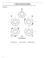
The cooktop you have purchased may have some or all of the items listed. Left rear control knob C. Downdraft fan knob B. Right front control knob 4 Right rear control knob F. Left front control knob D. Control Panel A B E C F D A. Power on indicator light E. PARTS AND FEATURES This manual covers different models.
The cooktop you have purchased may have some or all of the items listed. Left rear control knob C. Downdraft fan knob B. Right front control knob 4 Right rear control knob F. Left front control knob D. Control Panel A B E C F D A. Power on indicator light E. PARTS AND FEATURES This manual covers different models.

Use and Care Guide
Page 5
Model and serial number plate (located on some models) 5 Stainless steel frame (on outside bottom of cooktop) G G. Filter C. Downdraft vent cover B. Control panel I D E H A. Ceramic glass cooktop F D. Surface cooking area F. Power on indicator light H. Downdraft vent location E. Cooktop A B C I .
Model and serial number plate (located on some models) 5 Stainless steel frame (on outside bottom of cooktop) G G. Filter C. Downdraft vent cover B. Control panel I D E H A. Ceramic glass cooktop F D. Surface cooking area F. Power on indicator light H. Downdraft vent location E. Cooktop A B C I .
Use and Care Guide
Page 6
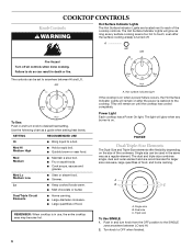
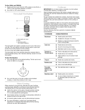
... hot. 6 A. The Hot Surface Indicator Lights will glow when any surface cooking area is too hot to touch, even after the power is on until the cooktop has cooled completely. Med Hi Medium High s Hold a rapid boil. s Simmer. Single size B. Triple size To Use SINGLE: 1. Turn knob to desired heat setting. REMEMBER: When cooktop is turned off all controls when done cooking. The light will glow as long as any burner is restored to the cooktop. A B C A. The controls...
... hot. 6 A. The Hot Surface Indicator Lights will glow when any surface cooking area is too hot to touch, even after the power is on until the cooktop has cooled completely. Med Hi Medium High s Hold a rapid boil. s Simmer. Single size B. Triple size To Use SINGLE: 1. Turn knob to desired heat setting. REMEMBER: When cooktop is turned off all controls when done cooking. The light will glow as long as any burner is restored to the cooktop. A B C A. The controls...
Use and Care Guide
Page 7
...'s instructions. Turn knob to prevent grease buildup. To Use Vent System: 1. s On ceramic glass models, use . Rough finishes may be cleaned often to OFF when finished. Cookware material is transferred, which affects cooking results. The downdraft vent cover and filter should not extend more information, contact your local agricultural department. Turn vent fan knob to medium heat settings. Canners should be used areas to cool. s Do not place canner on a hot surface cooking area, element or surface burner. A nonstick...
...'s instructions. Turn knob to prevent grease buildup. To Use Vent System: 1. s On ceramic glass models, use . Rough finishes may be cleaned often to OFF when finished. Cookware material is transferred, which affects cooking results. The downdraft vent cover and filter should not extend more information, contact your local agricultural department. Turn vent fan knob to medium heat settings. Canners should be used areas to cool. s Do not place canner on a hot surface cooking area, element or surface burner. A nonstick...
Use and Care Guide
Page 8
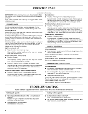
...: Clean while the cooktop is cool. Rub creme into surface with a damp paper towel or soft cloth. When replacing knobs, make sure all -purpose cleaner: Rinse with clean water and dry with soft, lint-free cloth. Continue rubbing until white film disappears. Do not use steel wool, abrasive cleansers or oven cleaner. Replace the fuse or reset the circuit breaker. s Is the appliance wired properly? See Installation Instructions. s On ceramic glass models...
...: Clean while the cooktop is cool. Rub creme into surface with a damp paper towel or soft cloth. When replacing knobs, make sure all -purpose cleaner: Rinse with clean water and dry with soft, lint-free cloth. Continue rubbing until white film disappears. Do not use steel wool, abrasive cleansers or oven cleaner. Replace the fuse or reset the circuit breaker. s Is the appliance wired properly? See Installation Instructions. s On ceramic glass models...
Use and Care Guide
Page 9
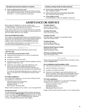
... size? s Use and maintenance procedures s Accessory and repair parts sales. See "Cooktop Controls" section. Cooktop Cleaner (ceramic glass models) Order Part Number 31464 Cooktop Protectant Order Part Number 31463 If you need replacement parts If you need to order replacement parts, we recommend that you still need help us or your appliance. For further assistance If you need further assistance, you can also look in the United States. s Referrals to the proper heat level? KitchenAid Canada...
... size? s Use and maintenance procedures s Accessory and repair parts sales. See "Cooktop Controls" section. Cooktop Cleaner (ceramic glass models) Order Part Number 31464 Cooktop Protectant Order Part Number 31463 If you need replacement parts If you need to order replacement parts, we recommend that you still need help us or your appliance. For further assistance If you need further assistance, you can also look in the United States. s Referrals to the proper heat level? KitchenAid Canada...
Use and Care Guide
Page 10
... the model and serial number label located on how to use your major appliance, to replace or repair house fuses, or to thermal shock of the ceramic glass cooktop ■ Surface unit elements This limited warranty does not cover: ITEMS EXCLUDED FROM WARRANTY 1. In the U.S.A., call 1-800-807-6777. 9/07 Keep this major appliance is not installed in -home service is reported to determine if another warranty applies. Service calls...
... the model and serial number label located on how to use your major appliance, to replace or repair house fuses, or to thermal shock of the ceramic glass cooktop ■ Surface unit elements This limited warranty does not cover: ITEMS EXCLUDED FROM WARRANTY 1. In the U.S.A., call 1-800-807-6777. 9/07 Keep this major appliance is not installed in -home service is reported to determine if another warranty applies. Service calls...
Parts Diagram
Page 1
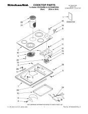
A COOKTOP PARTS For Models: KECD806RBL05, KECD806RWW05 (Black) (White on White) 30" ELECTRIC BUILT−IN DOWNDRDAFT COOKTOP 11−08 Litho in U.S.A. (amd) (eeb) 1 Part No. W10240405 Rev.
A COOKTOP PARTS For Models: KECD806RBL05, KECD806RWW05 (Black) (White on White) 30" ELECTRIC BUILT−IN DOWNDRDAFT COOKTOP 11−08 Litho in U.S.A. (amd) (eeb) 1 Part No. W10240405 Rev.
Parts Diagram
Page 2
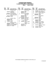
... RR Illus. Part No. DESCRIPTION 15 3183956 Seal, Switch Cover 16 3192439 Seal, Limiter (4) 17 4455917 Bracket, Mounting 18 Knob, Control 8286096BL Black 8286096WH White 19 Knob, Blower Switch 8286097BL Black 8286097WH White 20 Grille, Air 8285875 Black 8285826 White 21 3192530 Filter, Grease 22 9759094 Spring, Locator 23 W10137040 Gasket, Vent Shield 24 8286055 Light, Hot Surface Indicator 25 3193094 Plate, Cover 26 3400093 Screw 2 W10240405 No. COOKTOP PARTS For Models: KECD806RBL05, KECD806RWW05 (Black) (White on White) Illus...
... RR Illus. Part No. DESCRIPTION 15 3183956 Seal, Switch Cover 16 3192439 Seal, Limiter (4) 17 4455917 Bracket, Mounting 18 Knob, Control 8286096BL Black 8286096WH White 19 Knob, Blower Switch 8286097BL Black 8286097WH White 20 Grille, Air 8285875 Black 8285826 White 21 3192530 Filter, Grease 22 9759094 Spring, Locator 23 W10137040 Gasket, Vent Shield 24 8286055 Light, Hot Surface Indicator 25 3193094 Plate, Cover 26 3400093 Screw 2 W10240405 No. COOKTOP PARTS For Models: KECD806RBL05, KECD806RWW05 (Black) (White on White) Illus...
Parts Diagram
Page 3
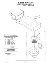
DESCRIPTION 1 W10169759 Bracket, Vent Shield 2 3196537 Screw 3 3192403 Bracket, Blower 4 3367670 Screw (4) 5 488130 Nut (4) 6 9760484 Ring, Inlet 7 9760485 Screen, Inlet 8 9760483 Adapter, Vent 9 W10109930 Blower Motor Assembly (Includes Fan Assembly) FOLLOWING PARTS NOT ILLUSTRATED Miscellaneous 8286642 Tape, Foam W10240405 3 BLOWER UNIT PARTS For Models: KECD806RBL05, KECD806RWW05 (Black) (White on White) Illus. Part No. No.
DESCRIPTION 1 W10169759 Bracket, Vent Shield 2 3196537 Screw 3 3192403 Bracket, Blower 4 3367670 Screw (4) 5 488130 Nut (4) 6 9760484 Ring, Inlet 7 9760485 Screen, Inlet 8 9760483 Adapter, Vent 9 W10109930 Blower Motor Assembly (Includes Fan Assembly) FOLLOWING PARTS NOT ILLUSTRATED Miscellaneous 8286642 Tape, Foam W10240405 3 BLOWER UNIT PARTS For Models: KECD806RBL05, KECD806RWW05 (Black) (White on White) Illus. Part No. No.


