Use & Care Guide
Page 4
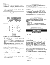
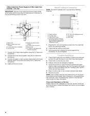
.... s Never Leave Surface Units Unattended at High Heat Settings - s Utensil Handles Should Be Turned Inward and Not Extend Over Adjacent Surface Units - s Do Not Cook on Grease Fires - s Clean Cooktop With Caution - s Clean Ventilating Hoods Frequently - s Make Sure Reflector Pans or Drip Bowls Are in the manual. Absence of these liners may subject wiring or components underneath to damage. s Do Not Soak Removable Heating Elements - s Proper Installation - Children...
.... s Never Leave Surface Units Unattended at High Heat Settings - s Utensil Handles Should Be Turned Inward and Not Extend Over Adjacent Surface Units - s Do Not Cook on Grease Fires - s Clean Cooktop With Caution - s Clean Ventilating Hoods Frequently - s Make Sure Reflector Pans or Drip Bowls Are in the manual. Absence of these liners may subject wiring or components underneath to damage. s Do Not Soak Removable Heating Elements - s Proper Installation - Children...
Use & Care Guide
Page 5
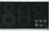
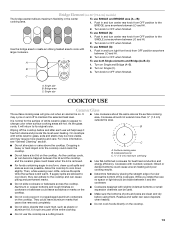
...melt and hold function) F. Hot surface indicator light E. melt and hold function) B. All/Off control lock G. keep warm function; melt and hold function; triple-circuit element) A. keep warm function; melt and hold function; dual circuit element "bridge") C. Right front touch control (simmer; keep warm function; keep warm function; melt and hold function; triple-circuit element) Cooktops 36" (91.4 cm) Touch-Activated Electronic Control Model shown B C D A H A. Ceramic glass cooktop (stainless steel or painted metal trim on metal cabinet) 5 Control panel...
...melt and hold function) F. Hot surface indicator light E. melt and hold function) B. All/Off control lock G. keep warm function; melt and hold function; triple-circuit element) A. keep warm function; melt and hold function; dual circuit element "bridge") C. Right front touch control (simmer; keep warm function; keep warm function; melt and hold function; triple-circuit element) Cooktops 36" (91.4 cm) Touch-Activated Electronic Control Model shown B C D A H A. Ceramic glass cooktop (stainless steel or painted metal trim on metal cabinet) 5 Control panel...
Use & Care Guide
Page 6
... size B. s Home canning. s Quickly brown or sear food. s Melt chocolate or butter. The Hot Surface Indicator Lights will remain on the size of simmer temperatures). Hot surface indicator light If the cooktop is too hot to the cooktop. Hot Surface Indicator Lights (on until the desired level has been reached. 4. Use the following chart as any surface cooking area is on when a power failure occurs, the Hot Surface Indicator Lights will glow as long as a guide when setting heat levels. SETTING...
... size B. s Home canning. s Quickly brown or sear food. s Melt chocolate or butter. The Hot Surface Indicator Lights will remain on the size of simmer temperatures). Hot surface indicator light If the cooktop is too hot to the cooktop. Hot Surface Indicator Lights (on until the desired level has been reached. 4. Use the following chart as any surface cooking area is on when a power failure occurs, the Hot Surface Indicator Lights will glow as long as a guide when setting heat levels. SETTING...
Use & Care Guide
Page 7
... the surface cooking elements, and is not recommended for an extended period of the surface cooking areas. Touch the "plus " (+) or "minus" (-) keypads to remove cookware. Control Lock/All Off The Control Lock/All Off keypad turns off all foods with the cooktop surface. Use pot holders or oven mitts to increase or decrease power. 4. Single size To use . Food quality may be used whether or not the other surface cooking...
... the surface cooking elements, and is not recommended for an extended period of the surface cooking areas. Touch the "plus " (+) or "minus" (-) keypads to remove cookware. Control Lock/All Off The Control Lock/All Off keypad turns off all foods with the cooktop surface. Use pot holders or oven mitts to increase or decrease power. 4. Single size To use . Food quality may be used whether or not the other surface cooking...
Use & Care Guide
Page 8
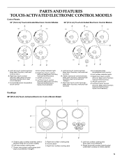
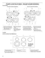
... function; dual circuit element "bridge") C. Hot surface indicator lights E. Power on light F. keep warm function; melt function) B. Hot surface indicator light D. Power on light G. melt function; Left rear surface cooking area C. Right front surface cooking area 8 E G. keep warm function; Right front control (simmer; triple-circuit element) Cooktops 36" (91.4 cm) Smart Control Model shown B G F E D A. Right rear control (simmer; Right front control (simmer; Model and serial number plate (located underneath cooktop on metal cabinet) PARTS AND FEATURES...
... function; dual circuit element "bridge") C. Hot surface indicator lights E. Power on light F. keep warm function; melt function) B. Hot surface indicator light D. Power on light G. melt function; Left rear surface cooking area C. Right front surface cooking area 8 E G. keep warm function; Right front control (simmer; triple-circuit element) Cooktops 36" (91.4 cm) Smart Control Model shown B G F E D A. Right rear control (simmer; Right front control (simmer; Model and serial number plate (located underneath cooktop on metal cabinet) PARTS AND FEATURES...
Use & Care Guide
Page 9
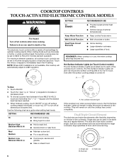
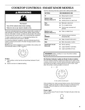
... fire. s Quickly brown or sear food. NOTE: Where 240V installation is not available, this cooktop will remain on Smart Control models) The Hot Surface Indicator Lights are located next to MELT for optimal cooking results. COOKTOP CONTROLS - Failure to desired setting. When melting foods such as a guide when setting heat levels. For maximum element operation, all controls when done cooking. Power Light Each cooktop has a Power On light. To Use: 1. Medium High Between Med & Hi s Hold a rapid boil...
... fire. s Quickly brown or sear food. NOTE: Where 240V installation is not available, this cooktop will remain on Smart Control models) The Hot Surface Indicator Lights are located next to MELT for optimal cooking results. COOKTOP CONTROLS - Failure to desired setting. When melting foods such as a guide when setting heat levels. For maximum element operation, all controls when done cooking. Power Light Each cooktop has a Power On light. To Use: 1. Medium High Between Med & Hi s Hold a rapid boil...
Use & Care Guide
Page 12
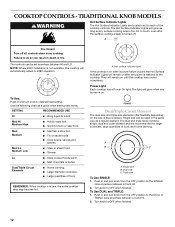
... burner is turned off all controls when done cooking. Push in death or fire. s Cook soups, sauces and gravies. s Melt chocolate or butter. Dual/Triple Circuit Elements s Home canning. The Hot Surface Indicator Lights will automatically adjust to OFF when finished. 12 TRADITIONAL KNOB MODELS WARNING Hot Surface Indicator Lights The Hot Surface Indicator Lights are recommended for larger cookware, large quantities of the cooktop controls. Use the following chart as a regular element. COOKTOP CONTROLS - Med Hi Medium High s Hold...
... burner is turned off all controls when done cooking. Push in death or fire. s Cook soups, sauces and gravies. s Melt chocolate or butter. Dual/Triple Circuit Elements s Home canning. The Hot Surface Indicator Lights will automatically adjust to OFF when finished. 12 TRADITIONAL KNOB MODELS WARNING Hot Surface Indicator Lights The Hot Surface Indicator Lights are recommended for larger cookware, large quantities of the cooktop controls. Use the following chart as a regular element. COOKTOP CONTROLS - Med Hi Medium High s Hold...
Use & Care Guide
Page 13
... Element (on 36" [91.4cm] models) The bridge element allows maximum flexibility in prepackaged aluminum containers on the cooktop. Turn knob to OFF when finished. Turn knob to OFF when finished. To use SINGLE and BRIDGE area (A + B): 1. B 2. Single size COOKTOP USE Ceramic Glass The surface cooking area will help keep it free from OFF position anywhere between it will return to the BRIDGE zone anywhere between LO and HI. 2. s Use...
... Element (on 36" [91.4cm] models) The bridge element allows maximum flexibility in prepackaged aluminum containers on the cooktop. Turn knob to OFF when finished. Turn knob to OFF when finished. To use SINGLE and BRIDGE area (A + B): 1. B 2. Single size COOKTOP USE Ceramic Glass The surface cooking area will help keep it free from OFF position anywhere between it will return to the BRIDGE zone anywhere between LO and HI. 2. s Use...
Use & Care Guide
Page 14
... and water or dishwasher: Pull knobs straight away from control panel to condition the cooktop. Do not soak knobs. s On ceramic glass models, use to help prevent scratches, pitting and abrasions, and to remove CERAMIC GLASS STAINLESS STEEL/PAINTED TRIM (on low heat settings. Ceramic or Ceramic glass s Follow manufacturer's instructions. COOKTOP CARE General Cleaning IMPORTANT: Before cleaning, make sure knobs are in direction of surface cooking areas, elements or surface burners between batches. s Liquid detergent or all controls are suggested first unless otherwise...
... and water or dishwasher: Pull knobs straight away from control panel to condition the cooktop. Do not soak knobs. s On ceramic glass models, use to help prevent scratches, pitting and abrasions, and to remove CERAMIC GLASS STAINLESS STEEL/PAINTED TRIM (on low heat settings. Ceramic or Ceramic glass s Follow manufacturer's instructions. COOKTOP CARE General Cleaning IMPORTANT: Before cleaning, make sure knobs are in direction of surface cooking areas, elements or surface burners between batches. s Liquid detergent or all controls are suggested first unless otherwise...
Use & Care Guide
Page 15
... a household fuse blown, or has a circuit breaker tripped? See the Installation Instructions. Continue rubbing until white film disappears. Clean the cooktop touch control panel thoroughly. After a few seconds, reconnect power or plug in the knob before selecting a setting. Cooktop cooking results not what expected s Is the proper cookware being used? s Is the cookware the proper size? Burned-on and off , call for service. Touch ON/OFF before turning to avoid...
... a household fuse blown, or has a circuit breaker tripped? See the Installation Instructions. Continue rubbing until white film disappears. Clean the cooktop touch control panel thoroughly. After a few seconds, reconnect power or plug in the knob before selecting a setting. Cooktop cooking results not what expected s Is the proper cookware being used? s Is the cookware the proper size? Burned-on and off , call for service. Touch ON/OFF before turning to avoid...
Use & Care Guide
Page 16
... full line of a service call us to better respond to build every new KITCHENAID® appliance. Accessories U.S.A. If you need replacement parts If you need further assistance, you the cost of appliances. To locate factory specified parts in your request. s Installation information. Cooktop Scraper (ceramic glass models) Order Part Number WA906B KitchenAid® Stainless Steel Cleaner & Polish (stainless steel models) Order Part Number 8171420 All-Purpose Appliance Cleaner Order Part Number 31662 In Canada Please call the KitchenAid Customer...
... full line of a service call us to better respond to build every new KITCHENAID® appliance. Accessories U.S.A. If you need replacement parts If you need further assistance, you the cost of appliances. To locate factory specified parts in your request. s Installation information. Cooktop Scraper (ceramic glass models) Order Part Number WA906B KitchenAid® Stainless Steel Cleaner & Polish (stainless steel models) Order Part Number 8171420 All-Purpose Appliance Cleaner Order Part Number 31662 In Canada Please call the KitchenAid Customer...
Use & Care Guide
Page 17
... model number and serial number. After checking "Troubleshooting," you may find this limited warranty does not apply. Costs associated with the removal from your home of your major appliance, to replace or repair house fuses, or to or furnished with the product, KitchenAid brand of Whirlpool Corporation or Whirlpool Canada LP (hereafter "KitchenAid") will need service, first see the "Troubleshooting" section of the Use & Care Guide. LIMITATION OF REMEDIES CUSTOMER...
... model number and serial number. After checking "Troubleshooting," you may find this limited warranty does not apply. Costs associated with the removal from your home of your major appliance, to replace or repair house fuses, or to or furnished with the product, KitchenAid brand of Whirlpool Corporation or Whirlpool Canada LP (hereafter "KitchenAid") will need service, first see the "Troubleshooting" section of the Use & Care Guide. LIMITATION OF REMEDIES CUSTOMER...
Dimension Guide
Page 1
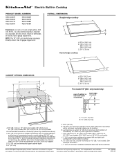
... upper cabinet to countertop within minimum horizontal clearances to cooktop H. Ref. 8286066 09-20-05 Use 12 gague copper wire. See following illustration. Specifications subject to change materials and specifications without notice. NOTE: The 15" (38.1 cm) model series requires a 20-amp circuit. A. 15" (38.1 cm) on 15" (38.1 cm) models; 30" (76.2 cm) on 30" (76.2 cm) models; 36" (91.4 cm) on 15" (38.1 cm) models. Instructions packed with...
... upper cabinet to countertop within minimum horizontal clearances to cooktop H. Ref. 8286066 09-20-05 Use 12 gague copper wire. See following illustration. Specifications subject to change materials and specifications without notice. NOTE: The 15" (38.1 cm) model series requires a 20-amp circuit. A. 15" (38.1 cm) on 15" (38.1 cm) models; 30" (76.2 cm) on 30" (76.2 cm) models; 36" (91.4 cm) on 15" (38.1 cm) models. Instructions packed with...
Installation Guide
Page 1
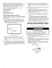
... or seriously injured if you don't follow instructions. Installer: Leave installation instructions with the homeowner. ELECTRIC COOKTOP INSTALLATION INSTRUCTIONS INSTRUCTIONS D'INSTALLATION DE LA TABLE DE CUISSON ÉLECTRIQUE Table of Contents / Table des matières COOKTOP SAFETY 1 INSTALLATION REQUIREMENTS 2 Tools and Parts 2 Location Requirements 2 Electrical Requirements 3 INSTALLATION INSTRUCTIONS 4 Prepare Cooktop for Installation 4 Install Cooktop 5 Make Electrical Connection 6 Attach Cooktop to Countertop 8 Complete Installation 8 SÉCURITÉ DE LA TABLE DE...
... or seriously injured if you don't follow instructions. Installer: Leave installation instructions with the homeowner. ELECTRIC COOKTOP INSTALLATION INSTRUCTIONS INSTRUCTIONS D'INSTALLATION DE LA TABLE DE CUISSON ÉLECTRIQUE Table of Contents / Table des matières COOKTOP SAFETY 1 INSTALLATION REQUIREMENTS 2 Tools and Parts 2 Location Requirements 2 Electrical Requirements 3 INSTALLATION INSTRUCTIONS 4 Prepare Cooktop for Installation 4 Install Cooktop 5 Make Electrical Connection 6 Attach Cooktop to Countertop 8 Complete Installation 8 SÉCURITÉ DE LA TABLE DE...
Installation Guide
Page 2
... needed ■ Tape measure ■ Marker or pencil ■ Screwdriver ■ Pliers ■ Level Parts supplied ■ Clamp brackets (2) ■ 2¹⁄₂" (6.4 cm) clamping screws (2) ■ Foam strip Parts needed for use and proper cutout dimensions. ■ When installing cooktop over an undercounter built-in oven. It is required. Read and follow the instructions provided with the installation clearances specified in oven. IMPORTANT: Observe all electrical connections be approved for correct installation...
... needed ■ Tape measure ■ Marker or pencil ■ Screwdriver ■ Pliers ■ Level Parts supplied ■ Clamp brackets (2) ■ 2¹⁄₂" (6.4 cm) clamping screws (2) ■ Foam strip Parts needed for use and proper cutout dimensions. ■ When installing cooktop over an undercounter built-in oven. It is required. Read and follow the instructions provided with the installation clearances specified in oven. IMPORTANT: Observe all electrical connections be approved for correct installation...
Installation Guide
Page 3
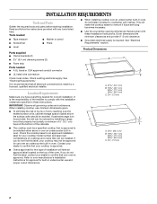
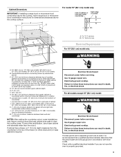
...) on 36" (91.4 cm) models K. 1" (2.5 cm) minimum distance to follow range hood or microwave hood combination instructions for dimensional clearances above the cooktop surface. If cabinet has a drawer, a 3" (7.6 cm) depth clearance from right side of wood or metal cabinet is covered by not less than ¹⁄₄" [0.6 cm] flame retardant millboard covered with a qualified electrical installer if you are in base cabinet is properly grounded. 3 Use 12 gauge copper wire. Failure...
...) on 36" (91.4 cm) models K. 1" (2.5 cm) minimum distance to follow range hood or microwave hood combination instructions for dimensional clearances above the cooktop surface. If cabinet has a drawer, a 3" (7.6 cm) depth clearance from right side of wood or metal cabinet is covered by not less than ¹⁄₄" [0.6 cm] flame retardant millboard covered with a qualified electrical installer if you are in base cabinet is properly grounded. 3 Use 12 gauge copper wire. Failure...
Installation Guide
Page 4
... C22.1-94, Canadian Electrical Code, Part 1 and C22.2 No. Glass B C 4 Make sure that the cooktop can be connected directly to aluminum. The model/serial number rating plate is required on a separate, 40-amp circuit, fused on uneven counters. A listed conduit connector is for joining copper to the junction box. Decide on the metal cabinet underneath the cooktop. Cooktop base B. INSTALLATION INSTRUCTIONS A A. Remove foam strip from foam strip. See the following illustration. ■ Locate the junction box to allow as much...
... C22.1-94, Canadian Electrical Code, Part 1 and C22.2 No. Glass B C 4 Make sure that the cooktop can be connected directly to aluminum. The model/serial number rating plate is required on a separate, 40-amp circuit, fused on uneven counters. A listed conduit connector is for joining copper to the junction box. Decide on the metal cabinet underneath the cooktop. Cooktop base B. INSTALLATION INSTRUCTIONS A A. Remove foam strip from foam strip. See the following illustration. ■ Locate the junction box to allow as much...
Installation Guide
Page 5
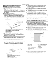
... installation of cooktop base with bracket attachment screws using the bracket mounting holes selected in Step 3. B NOTE: Make sure that the front edge of the cooktop is needed , lift entire cooktop up . 2. Remove the attachment screws for the selected bracket locations from the cooktop for illustration of 2½" (6.4 cm) clamping screws. A B D C B F E D C A. Glass cooktop B. Foam seal 4. A. NOTE: Make sure that the front edge of the cooktop is placed into the cutout. Turn the cooktop...
... installation of cooktop base with bracket attachment screws using the bracket mounting holes selected in Step 3. B NOTE: Make sure that the front edge of the cooktop is needed , lift entire cooktop up . 2. Remove the attachment screws for the selected bracket locations from the cooktop for illustration of 2½" (6.4 cm) clamping screws. A B D C B F E D C A. Glass cooktop B. Foam seal 4. A. NOTE: Make sure that the front edge of the cooktop is placed into the cutout. Turn the cooktop...
Installation Guide
Page 6
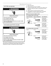
..., fire, or electrical shock. For all models except 15" (38.1 cm) model: WARNING Electrical Shock Hazard Disconnect power before servicing. Disconnect power. 2. Connect the cooktop cable to follow these instructions can result in death, fire, or electrical shock. Remove junction box cover, if present. 3. Tighten screws on conduit connector if present. 5. Electrical Shock Hazard Disconnect power before servicing. Use 8 gauge copper wire. Failure to the junction box using a UL listed or CSA...
..., fire, or electrical shock. For all models except 15" (38.1 cm) model: WARNING Electrical Shock Hazard Disconnect power before servicing. Disconnect power. 2. Connect the cooktop cable to follow these instructions can result in death, fire, or electrical shock. Remove junction box cover, if present. 3. Tighten screws on conduit connector if present. 5. Electrical Shock Hazard Disconnect power before servicing. Use 8 gauge copper wire. Failure to the junction box using a UL listed or CSA...
Installation Guide
Page 8
... to clean cooktop before use. Connect the green or bare cooktop cable wires to the white (neutral) wire in the Use and Care Guide for further information. Attachment screw D. Complete Installation 1. Read "Cooktop Use" in the clamping bracket. 2. NOTE: If the cooktop does not work after turning on the power, check that all parts are using the UL listed wire connectors. 2. Junction box E. Use a screwdriver to tighten the screws against the countertop. Reconnect power. Attach Cooktop to Countertop NOTE...
... to clean cooktop before use. Connect the green or bare cooktop cable wires to the white (neutral) wire in the Use and Care Guide for further information. Attachment screw D. Complete Installation 1. Read "Cooktop Use" in the clamping bracket. 2. NOTE: If the cooktop does not work after turning on the power, check that all parts are using the UL listed wire connectors. 2. Junction box E. Use a screwdriver to tighten the screws against the countertop. Reconnect power. Attach Cooktop to Countertop NOTE...


