
Instruction Manual
Page 6
... finalized can 't be played. (For the finalization process refer to damage than a normal music CD. Disc accessories Don't use a disc with . on the package etc. • Don't stick tape etc. Also, don't use disc type accessories. Use a CD-R/RW, DVDR/RW, or DVD+R/RW after removing them with coloring on it after...
... finalized can 't be played. (For the finalization process refer to damage than a normal music CD. Disc accessories Don't use a disc with . on the package etc. • Don't stick tape etc. Also, don't use disc type accessories. Use a CD-R/RW, DVDR/RW, or DVD+R/RW after removing them with coloring on it after...
Instruction Manual
Page 11
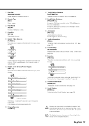
... Traffic Information function On or Off. (see page 30) w Screen Setup [SCREEN] key Displays the Screen Setup or Angle Setup screen. (see page 14) * Optional accessory Hold down more than 1 second to turn power supply On. 7 Volume Controls [5]/[∞] key When a disc has already been loaded (when the "red" disc indicator...
... Traffic Information function On or Off. (see page 30) w Screen Setup [SCREEN] key Displays the Screen Setup or Angle Setup screen. (see page 14) * Optional accessory Hold down more than 1 second to turn power supply On. 7 Volume Controls [5]/[∞] key When a disc has already been loaded (when the "red" disc indicator...
Instruction Manual
Page 70
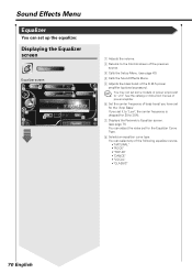
... boost to 30%. 7 Displays the Parametric Equalizer screen. (see page 43) 4 Calls the Sound Effects Menu. 5 Adjusts the bass boost of the B.M.S power amplifier (optional accessory). Sound Effects Menu Equalizer You can select any of the following equalizer curves. • "NATURAL" • "ROCK" • "TOP 40" • "DANCE" • "VOCAL" •...
... boost to 30%. 7 Displays the Parametric Equalizer screen. (see page 43) 4 Calls the Sound Effects Menu. 5 Adjusts the bass boost of the B.M.S power amplifier (optional accessory). Sound Effects Menu Equalizer You can select any of the following equalizer curves. • "NATURAL" • "ROCK" • "TOP 40" • "DANCE" • "VOCAL" •...

Instruction Manual
Page 76
Before Installation Accessories 1 2 3 4 5 6 7 8 9 0 - ..........1 ..........1 = ..........1 ~ ..........1 ! ..........1 @ ..........1 # ..........2 $ ..........4 % ..........4 ^ ..........2 76 English ..........2 ..........4 ..........4 ..........4 ..........2 ..........2 ..........4 ..........4 ..........1
Before Installation Accessories 1 2 3 4 5 6 7 8 9 0 - ..........1 ..........1 = ..........1 ~ ..........1 ! ..........1 @ ..........1 # ..........2 $ ..........4 % ..........4 ^ ..........2 76 English ..........2 ..........4 ..........4 ..........4 ..........2 ..........2 ..........4 ..........4 ..........1
Instruction Manual
Page 78
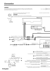
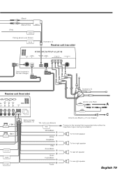
...reverse lamp harness Monitor unit Ground wire (Black) - (To car chassis) C Battery wire (Yellow) ( 5A ) B BATT Antenna Cord Accessory 5 Disc Changer etc. Always connect those wires to its power control terminal. When using the supplied relay connector. 2CAUTION For the sake of ... the booster amplifier of the film-type antenna. Motor antenna control wire (Blue/White) Power control wire (Blue) External amplifier control wire (Pink/Black) Accessory 2 Accessory 3 FM/AM antenna input AV INPUT 1 VIDEO L R FM /AM ANTENNA AV INPUT 2 VIDEO L R AV OUTPUT L VI R CEN Ignition key...
...reverse lamp harness Monitor unit Ground wire (Black) - (To car chassis) C Battery wire (Yellow) ( 5A ) B BATT Antenna Cord Accessory 5 Disc Changer etc. Always connect those wires to its power control terminal. When using the supplied relay connector. 2CAUTION For the sake of ... the booster amplifier of the film-type antenna. Motor antenna control wire (Blue/White) Power control wire (Blue) External amplifier control wire (Pink/Black) Accessory 2 Accessory 3 FM/AM antenna input AV INPUT 1 VIDEO L R FM /AM ANTENNA AV INPUT 2 VIDEO L R AV OUTPUT L VI R CEN Ignition key...
Instruction Manual
Page 79
... left speaker To rear right speaker English 79 (Black) + (Black/White) CENTER (Pink) REVERSE Parking sensor wire (Green) PRK SW Accessory 4 Receiver unit (rear side) TO MONITOR CENTER SP (BLACK) SENSOR LINE TO MONITOR TO 5L I/F (WHITE) ...TO NAVIGATION I/F TO TV ANTENNA Cable (included in the disc changer) Receiver unit (front side) Accessory ! CONT P CONT EXT CONT. Wiring harness (Accessory 1) TEL mute wire (Brown) MUTE White/Black + White Gray/Black + Gray Green/Black + Green Purple/Black + Purple Ignition ...
... left speaker To rear right speaker English 79 (Black) + (Black/White) CENTER (Pink) REVERSE Parking sensor wire (Green) PRK SW Accessory 4 Receiver unit (rear side) TO MONITOR CENTER SP (BLACK) SENSOR LINE TO MONITOR TO 5L I/F (WHITE) ...TO NAVIGATION I/F TO TV ANTENNA Cable (included in the disc changer) Receiver unit (front side) Accessory ! CONT P CONT EXT CONT. Wiring harness (Accessory 1) TEL mute wire (Brown) MUTE White/Black + White Gray/Black + Gray Green/Black + Green Purple/Black + Purple Ignition ...

Instruction Manual
Page 81
... sure that the unit is unstable, it in place. Tapping screw (ø4×16 mm) (Accessory 9) English 81 Attach the installation brackets 0 to the audio board. Installation brackets (Accessory 0) Sems bolts (M4×8 mm) (Accessory 8) 2. Use the tapping screw 9 to secure the hideaway unit to the sides of the mounting sleeve with a screwdriver...
... sure that the unit is unstable, it in place. Tapping screw (ø4×16 mm) (Accessory 9) English 81 Attach the installation brackets 0 to the audio board. Installation brackets (Accessory 0) Sems bolts (M4×8 mm) (Accessory 8) 2. Use the tapping screw 9 to secure the hideaway unit to the sides of the mounting sleeve with a screwdriver...
Instruction Manual
Page 82
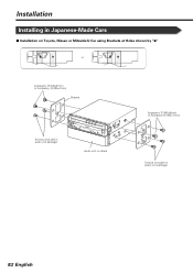
Installation Installing in Japanese-Made Cars ■ Installation on Toyota, Nissan or Mitsubishi Car using Brackets at Holes shown by "¶" or Accessory $ (M5×6mm) or Accessory % (M5×7mm) Bracket Screws (included in audio unit package) Audio unit or others Accessory $ (M5×6mm) or Accessory % (M5×7mm) Screws (included in audio unit package) 82 English
Installation Installing in Japanese-Made Cars ■ Installation on Toyota, Nissan or Mitsubishi Car using Brackets at Holes shown by "¶" or Accessory $ (M5×6mm) or Accessory % (M5×7mm) Bracket Screws (included in audio unit package) Audio unit or others Accessory $ (M5×6mm) or Accessory % (M5×7mm) Screws (included in audio unit package) 82 English
Instruction Manual
Page 83
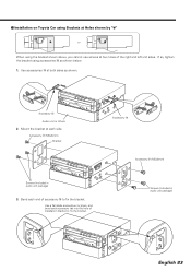
...using Brackets at Holes shown by "¶" or When using accessories # as shown. If so, tighten the bracket using the bracket shown above, you cannot use screws at each accessory tab into the hole of installation bracket to fix the bracket. Accessory # Audio unit or others 2. Use a flat-blade ...screwdriver or pliers, and bend each side. Mount the bracket at two holes of accessory # to fix the bracket. Bend each ...
...using Brackets at Holes shown by "¶" or When using accessories # as shown. If so, tighten the bracket using the bracket shown above, you cannot use screws at each accessory tab into the hole of installation bracket to fix the bracket. Accessory # Audio unit or others 2. Use a flat-blade ...screwdriver or pliers, and bend each side. Mount the bracket at two holes of accessory # to fix the bracket. Bend each ...
Instruction Manual
Page 84
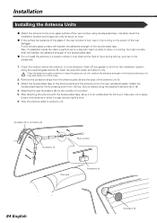
...with water and allow to receiver unit. Attach the double-sided tape by turning on the power of the rear defogger. Attaching the seal (Accessory %) on once. ¶ If the surface temperature of the glass of the double-sided tape. ¶ Do not install the antenna ...in a location where it may also cause it to be attached. Wire the antenna cable to dry. Accessory @ or Accessory # Accessory ! Rear window Rear seat Accessory $ 84 English Accessory % Installation Installing the Antenna Units ¶ Attach the antenna to sit undisturbed for 24 hours. Clean the glass thoroughly...
...with water and allow to receiver unit. Attach the double-sided tape by turning on the power of the rear defogger. Attaching the seal (Accessory %) on once. ¶ If the surface temperature of the glass of the double-sided tape. ¶ Do not install the antenna ...in a location where it may also cause it to be attached. Wire the antenna cable to dry. Accessory @ or Accessory # Accessory ! Rear window Rear seat Accessory $ 84 English Accessory % Installation Installing the Antenna Units ¶ Attach the antenna to sit undisturbed for 24 hours. Clean the glass thoroughly...

Instruction Manual
Page 85
... unit all the way out with integral washer (M4 × 6) on each side, as shown in the same manner. ˙ Removing the Unit 1. Lock Catch Accessory 7 Accessory 7 English 85 Remove the Hex-head screw with your hands, being careful not to drop it forward as shown. 4. Refer to avoid injury from the...
... unit all the way out with integral washer (M4 × 6) on each side, as shown in the same manner. ˙ Removing the Unit 1. Lock Catch Accessory 7 Accessory 7 English 85 Remove the Hex-head screw with your hands, being careful not to drop it forward as shown. 4. Refer to avoid injury from the...


