Instruction Manual
Page 2
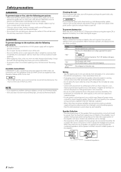
... than the unit's fuse capacity. (Use a power wiring cord with a diameter of 8 mm² (AWG 8) or greater.) • When more than one set of speakers are less than the output power of the amplifier will cause smoke to be working right, consult your Kenwood dealer. Speaker Selection • The rated input power of the speakers that are explained in Watts) of the amplifier. Using a fuse with the prescribed rating. NOTE Turn the power OFF...
... than the unit's fuse capacity. (Use a power wiring cord with a diameter of 8 mm² (AWG 8) or greater.) • When more than one set of speakers are less than the output power of the amplifier will cause smoke to be working right, consult your Kenwood dealer. Speaker Selection • The rated input power of the speakers that are explained in Watts) of the amplifier. Using a fuse with the prescribed rating. NOTE Turn the power OFF...
Instruction Manual
Page 3
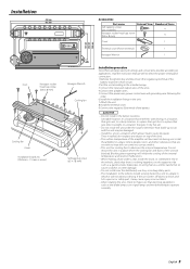
...Part name Self-tapping screws (ø5 × 18 mm) Hexagon socket head cap screw (M4 × 8 mm) External View Number of Items 4 4 Cover 1 Terminal cover (Power terminal) 1 Hexagon Wrench 1 Installation procedure Since there are large variety of the internal temperature and result in malfunction. • When making a hole under the carpet. Install the amplifier..., turn signal lamps and windshield wipers operate normally. terminal of the battery to prevent short circuits. 2.Set the unit according to the intended usage. 3.Connect the input and output wires of the amplifier will...
...Part name Self-tapping screws (ø5 × 18 mm) Hexagon socket head cap screw (M4 × 8 mm) External View Number of Items 4 4 Cover 1 Terminal cover (Power terminal) 1 Hexagon Wrench 1 Installation procedure Since there are large variety of the internal temperature and result in malfunction. • When making a hole under the carpet. Install the amplifier..., turn signal lamps and windshield wipers operate normally. terminal of the battery to prevent short circuits. 2.Set the unit according to the intended usage. 3.Connect the input and output wires of the amplifier will...
Instruction Manual
Page 4
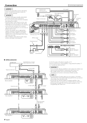
... sound is not output normally, immediately turn power off and check connections. • Be sure to turn the power off before changing the setting of any switch. • If the fuse blows, check wires for shorts, then replace the fuse with one of them . 2CAUTION • Do not connect 2 Master amplifiers to the Center Unit. CENTER UNIT (CD receiver, etc.) Lead terminal* Power control wire Terminal cover Battery wire* Protective Fuse* ��� RCA cable* RCA cable ground terminal ��� B channel input A channel input...
... sound is not output normally, immediately turn power off and check connections. • Be sure to turn the power off before changing the setting of any switch. • If the fuse blows, check wires for shorts, then replace the fuse with one of them . 2CAUTION • Do not connect 2 Master amplifiers to the Center Unit. CENTER UNIT (CD receiver, etc.) Lead terminal* Power control wire Terminal cover Battery wire* Protective Fuse* ��� RCA cable* RCA cable ground terminal ��� B channel input A channel input...
Instruction Manual
Page 5
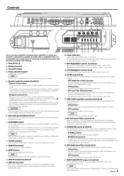
...; is amplifier B. Set to this switch. • STEREO position: The amplifier can be no less than the frequency set to the pre-output level of amplifier B using an RCA cable with the Amplifier Control are used. (Make connections to the LEFT channel 9 and the RIGHT channel · SPEAKER OUTPUT terminals.) The speakers to be connected should be used as amplifier A and the other is set the Master amplifier, connect it On again. 8 TO H/U terminal After you use the unit as a high-output monaural amplifier, bridged connections are NOT reset. ! Controls...
...; is amplifier B. Set to this switch. • STEREO position: The amplifier can be no less than the frequency set to the pre-output level of amplifier B using an RCA cable with the Amplifier Control are used. (Make connections to the LEFT channel 9 and the RIGHT channel · SPEAKER OUTPUT terminals.) The speakers to be connected should be used as amplifier A and the other is set the Master amplifier, connect it On again. 8 TO H/U terminal After you use the unit as a high-output monaural amplifier, bridged connections are NOT reset. ! Controls...
Instruction Manual
Page 6
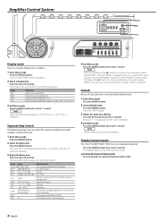
... 'Display mode' Bass Center Frequency Bass level Bass Q Factor When the bass extend is set values are switched in the following explains how to its default Press the [3] button for at least 2 seconds. Treble Center Frequency Treble level Volume offset The Fahrenheit or Centigrade temperature unit can be initialized. To call the Amplifier Control's values, hold down the [2] button 3 or more seconds during ID number display ("AMP...
... 'Display mode' Bass Center Frequency Bass level Bass Q Factor When the bass extend is set values are switched in the following explains how to its default Press the [3] button for at least 2 seconds. Treble Center Frequency Treble level Volume offset The Fahrenheit or Centigrade temperature unit can be initialized. To call the Amplifier Control's values, hold down the [2] button 3 or more seconds during ID number display ("AMP...
Instruction Manual
Page 7
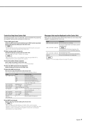
...) 0 - 7 Treble Center Frequency Treble level Volume offset Select an ID number of the amp you use . 6 Exit AMP Control mode Releases the Amp Control mode by 20%. When the speaker output is overheating. "AMP OFF" When you use the Amp Control in contact with the Amp Control, an error status of the amplifier is set a value of each item on the Center Unit. NOTE Number "×" on the Operation Manual of the Center Unit, and when you...
...) 0 - 7 Treble Center Frequency Treble level Volume offset Select an ID number of the amp you use . 6 Exit AMP Control mode Releases the Amp Control mode by 20%. When the speaker output is overheating. "AMP OFF" When you use the Amp Control in contact with the Amp Control, an error status of the amplifier is set a value of each item on the Center Unit. NOTE Number "×" on the Operation Manual of the Center Unit, and when you...
Instruction Manual
Page 8
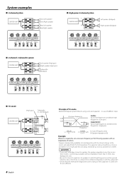
...Cut of Frequency (Hz) R=Speaker Impedance (Ω) Example: When it is required to set a crossover frequency of 120 Hz using a coil and capacitor...in a drop of the combined impedance with an impedance lower than 4 ohms may damage the unit. • Be sure to connect capacitors to speakers to which high frequencies will be no less than 4 ohms. Connecting a speaker with the subwoofer...65533;� High-power 2-channel system � �� CENTER UNIT � �� Left speaker (Bridged) Right speaker (Bridged) �� �...
...Cut of Frequency (Hz) R=Speaker Impedance (Ω) Example: When it is required to set a crossover frequency of 120 Hz using a coil and capacitor...in a drop of the combined impedance with an impedance lower than 4 ohms may damage the unit. • Be sure to connect capacitors to speakers to which high frequencies will be no less than 4 ohms. Connecting a speaker with the subwoofer...65533;� High-power 2-channel system � �� CENTER UNIT � �� Left speaker (Bridged) Right speaker (Bridged) �� �...
Instruction Manual
Page 9
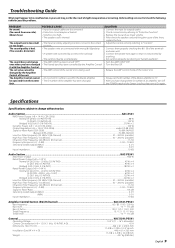
.... The Amplifier Control cannot be activated. • Volume is too high. • The speaker cord is shorted. • The input sensitivity adjusting control is not pinched by anything. • Set switches properly by the Amplifier Control of the unit. POSSIBLE CAUSE • Input (or output) cables are disconnected. • Protection circuit may be operated from one side.) (Blown fuse.) The output level is distorted.) The sound does not change without notice. Audio Section...KAC-X541 RMS Power Output...
.... The Amplifier Control cannot be activated. • Volume is too high. • The speaker cord is shorted. • The input sensitivity adjusting control is not pinched by anything. • Set switches properly by the Amplifier Control of the unit. POSSIBLE CAUSE • Input (or output) cables are disconnected. • Protection circuit may be operated from one side.) (Blown fuse.) The output level is distorted.) The sound does not change without notice. Audio Section...KAC-X541 RMS Power Output...


