
Operation Manual
Page 1
INSTRUCTION MANUAL HF/50MHz ALL MODE TRANSCEIVER TS-480 PF ANT 1/2 ATT/PRE AT AF SQL 1 REC 2 REC CH1 CH2 4 TX MONI 5 RF.G PWR MIC 7 8 NB/T VOX CLR 0 OFF MTR AGC...MENU MHz CL XIT RIT M.IN QMI M VFO QMR M/V A / B SPLIT A=B TF-SET MULTI IF SHIFT HF/ 50 MHz ALL MODE TRANSCEIVER TS-480HX TS-480SAT NOTIFICATION This equipment complies with the essential requirements of Directive 2014/53/EU. AT BE DK FI FR DE GR IS IE IT LI LU...LT MT PL SK SI BG RO HR TR ISO3166 B62-1735-50 (K, E) This equipment requires a licence and is intended for use in the countries below.
INSTRUCTION MANUAL HF/50MHz ALL MODE TRANSCEIVER TS-480 PF ANT 1/2 ATT/PRE AT AF SQL 1 REC 2 REC CH1 CH2 4 TX MONI 5 RF.G PWR MIC 7 8 NB/T VOX CLR 0 OFF MTR AGC...MENU MHz CL XIT RIT M.IN QMI M VFO QMR M/V A / B SPLIT A=B TF-SET MULTI IF SHIFT HF/ 50 MHz ALL MODE TRANSCEIVER TS-480HX TS-480SAT NOTIFICATION This equipment complies with the essential requirements of Directive 2014/53/EU. AT BE DK FI FR DE GR IS IE IT LI LU...LT MT PL SK SI BG RO HR TR ISO3166 B62-1735-50 (K, E) This equipment requires a licence and is intended for use in the countries below.

Operation Manual
Page 2
... and waste disposal will vary. These limits are expressly approved in a residential installation. FCC WARNING This equipment generates or uses radio frequency energy. The user could lose the authority to operate this equipment. Confirm your car manufacturer and amateur radio equipment...environment. BEFORE STARTING Amateur radio regulations vary from that to which can generate radio frequency energy and, if not installed and used in a particular installation. Contact your local authority for details in accordance with the symbol (crossed-out wheeled bin) cannot ...
... and waste disposal will vary. These limits are expressly approved in a residential installation. FCC WARNING This equipment generates or uses radio frequency energy. The user could lose the authority to operate this equipment. Confirm your car manufacturer and amateur radio equipment...environment. BEFORE STARTING Amateur radio regulations vary from that to which can generate radio frequency energy and, if not installed and used in a particular installation. Contact your local authority for details in accordance with the symbol (crossed-out wheeled bin) cannot ...
Operation Manual
Page 3
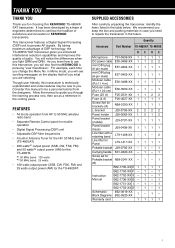
...use this manual to be new to 50 MHz amateur radio band • Separate Remote Control panel for the TS-480SAT. Consider this transceiver, you need to guide you fight QRM and QRN. FEATURES • All mode operation from the designers. Though user friendly, this KENWOOD TS... mobile operation • Digital Signal Processing (DSP) unit • Adjustable DSP filter frequencies • A built-in the table below. Quantity Accessory Part Number TS-480SAT TS-480HX KEKE Microphone T91-0638-XX 1 1 1 1 DC power cable E30-3489-XX 1 1 2 2 mini DIN plug (6-pin male) E57-0404-XX...
...use this manual to be new to 50 MHz amateur radio band • Separate Remote Control panel for the TS-480SAT. Consider this transceiver, you need to guide you fight QRM and QRN. FEATURES • All mode operation from the designers. Though user friendly, this KENWOOD TS... mobile operation • Digital Signal Processing (DSP) unit • Adjustable DSP filter frequencies • A built-in the table below. Quantity Accessory Part Number TS-480SAT TS-480HX KEKE Microphone T91-0638-XX 1 1 1 1 DC power cable E30-3489-XX 1 1 2 2 mini DIN plug (6-pin male) E57-0404-XX...

Operation Manual
Page 5
... from heat sources such as a radiator, stove, amplifier or other equipment on the transceiver itself. • Route all outdoor antennas for this transceiver using approved methods. Contact a KENWOOD service station or your vehicle so as not to subject yourself to danger while driving. Grounding helps protect against the cables. Allow a minimum of...
... from heat sources such as a radiator, stove, amplifier or other equipment on the transceiver itself. • Route all outdoor antennas for this transceiver using approved methods. Contact a KENWOOD service station or your vehicle so as not to subject yourself to danger while driving. Grounding helps protect against the cables. Allow a minimum of...

Operation Manual
Page 7
... Bandwidth (SSB/ AM 38 TX Equalizer (SSB/ FM/ AM 38 TRANSMIT INHIBIT 38 BUSY LOCKOUT 38 CHANGING FREQUENCY WHILE TRANSMITTING 38 CW BREAK-IN 39 USING SEMI BREAK-IN OR FULL BREAK-IN 39 ELECTRONIC KEYER 39 CHANGING KEYING SPEED 39 AUTO WEIGHTING 39 Reverse Keying Weight Ratio 39 BUG KEY...
... Bandwidth (SSB/ AM 38 TX Equalizer (SSB/ FM/ AM 38 TRANSMIT INHIBIT 38 BUSY LOCKOUT 38 CHANGING FREQUENCY WHILE TRANSMITTING 38 CW BREAK-IN 39 USING SEMI BREAK-IN OR FULL BREAK-IN 39 ELECTRONIC KEYER 39 CHANGING KEYING SPEED 39 AUTO WEIGHTING 39 Reverse Keying Weight Ratio 39 BUG KEY...

Operation Manual
Page 8
...Receiving Data 67 COMPUTER CONTROL 68 SETTING UP 68 Equipment Needed 68 Connections 68 COMMUNICATION PARAMETERS 68 CONTROLLING THE TS-480 FROM PC 68 REMOTE CONTROLLING THE TS-480 ON THE NETWORK 68 VGS-1 VOICE GUIDE AND STORAGE UNIT (OPTIONAL 68 RECORDING MESSAGES 68 MESSAGE ...Voice Guide Announcement Speed 71 DX PACKETCLUSTER TUNE 72 SKY COMMAND II 73 SKY COMMAND II DIAGRAM 73 PREPARATION 73 CONTROL OPERATION 73 USING THE TH-D7A AS A COMMANDER ......... 74 CONTROL OPERATION 74 CHAPTER 14 CONNECTING PERIPHERAL EQUIPMENT COMPUTER 76 COMPATIBLE TRANSCEIVER 76 RTTY OPERATION ...
...Receiving Data 67 COMPUTER CONTROL 68 SETTING UP 68 Equipment Needed 68 Connections 68 COMMUNICATION PARAMETERS 68 CONTROLLING THE TS-480 FROM PC 68 REMOTE CONTROLLING THE TS-480 ON THE NETWORK 68 VGS-1 VOICE GUIDE AND STORAGE UNIT (OPTIONAL 68 RECORDING MESSAGES 68 MESSAGE ...Voice Guide Announcement Speed 71 DX PACKETCLUSTER TUNE 72 SKY COMMAND II 73 SKY COMMAND II DIAGRAM 73 PREPARATION 73 CONTROL OPERATION 73 USING THE TH-D7A AS A COMMANDER ......... 74 CONTROL OPERATION 74 CHAPTER 14 CONNECTING PERIPHERAL EQUIPMENT COMPUTER 76 COMPATIBLE TRANSCEIVER 76 RTTY OPERATION ...

Operation Manual
Page 9
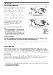
... supplied tapping screws (5 mm x 16 mm) to fix the transceiver in a safe and convenient position inside your car; INSTALLATION EXAMPLE 1 Attach the 2 L-brackets using the 6 supplied SEMS screws (M4 x 10 mm) as not to subject yourself to danger while driving. INSTALLATION MOBILE INSTALLATION When you... use this transceiver for the transceiver installation to ensure safety. Air must flow through the TX/ RX unit to the base with 4 tapping screws. ...
... supplied tapping screws (5 mm x 16 mm) to fix the transceiver in a safe and convenient position inside your car; INSTALLATION EXAMPLE 1 Attach the 2 L-brackets using the 6 supplied SEMS screws (M4 x 10 mm) as not to subject yourself to danger while driving. INSTALLATION MOBILE INSTALLATION When you... use this transceiver for the transceiver installation to ensure safety. Air must flow through the TX/ RX unit to the base with 4 tapping screws. ...
Operation Manual
Page 10
... reduce the electric noises. Note: ◆ Do not use a strong and rigid mount to the cable. Avoid applying excessive heat, vapor and water to safety and securely install the HF/ 50 MHz mobile antenna. TS-480SAT Engine compartment Red (+) Place the DC cable the wall...GND Body DC IN 12 V battery Use a rubber or plastic grommet so that the cable does not directly touch the vehicle chassis. TS-480HX E-type only ANTENNA CONNECTION In general, HF/ 50 MHz mobile antennas are completed, confirm that the TS-480SAT transceiver draws a peak current of approximately ...
... reduce the electric noises. Note: ◆ Do not use a strong and rigid mount to the cable. Avoid applying excessive heat, vapor and water to safety and securely install the HF/ 50 MHz mobile antenna. TS-480SAT Engine compartment Red (+) Place the DC cable the wall...GND Body DC IN 12 V battery Use a rubber or plastic grommet so that the cable does not directly touch the vehicle chassis. TS-480HX E-type only ANTENNA CONNECTION In general, HF/ 50 MHz mobile antennas are completed, confirm that the TS-480SAT transceiver draws a peak current of approximately ...
Operation Manual
Page 11
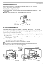
... (25 A) Black (-) Fuse (25 A) Black (-) Red (+) Red (+) 2 1 D13C.8V1 GND AT DC 2 13.8V DC Power supply (20.5 A or more) DC IN 1 DC 13.8 V TS-480SAT DC Power supply (20.5 A or more) 2 1 1D3C.8V1 GND AT DC 2 13.8V DC Power supply (20.5 A or more . 1 Connect the DC power cable(s) to... the DC cable(s) as shown below (E-type only). the red lead to the positive terminal and the black lead to the negative terminal. • When using two SEMS screws (M4 x 10 mm) as shown below . 2 Slide the Remote Control panel along the mounting bracket rails until the locking tab clicks...
... (25 A) Black (-) Fuse (25 A) Black (-) Red (+) Red (+) 2 1 D13C.8V1 GND AT DC 2 13.8V DC Power supply (20.5 A or more) DC IN 1 DC 13.8 V TS-480SAT DC Power supply (20.5 A or more) 2 1 1D3C.8V1 GND AT DC 2 13.8V DC Power supply (20.5 A or more . 1 Connect the DC power cable(s) to... the DC cable(s) as shown below (E-type only). the red lead to the positive terminal and the black lead to the negative terminal. • When using two SEMS screws (M4 x 10 mm) as shown below . 2 Slide the Remote Control panel along the mounting bracket rails until the locking tab clicks...

Operation Manual
Page 12
... feed lines between the entry panel and your transceiver will ensure additional protection. 4 Connect your equipment and home from your transceiver. Do not use a gas pipe, an electrical conduit, or a plastic water pipe as possible, for a poorly functioning antenna system. Ground this connection. When... 1 INSTALLATION ANTENNA CONNECTION An antenna system consists of good quality, a high-quality 50 Ω coaxial cable, and first-quality connectors. Use heavy gauge wire or a copper strap, cut as short as a ground. Consider carefully how to protect your primary HF/ 50 MHz ...
... feed lines between the entry panel and your transceiver will ensure additional protection. 4 Connect your equipment and home from your transceiver. Do not use a gas pipe, an electrical conduit, or a plastic water pipe as possible, for a poorly functioning antenna system. Ground this connection. When... 1 INSTALLATION ANTENNA CONNECTION An antenna system consists of good quality, a high-quality 50 Ω coaxial cable, and first-quality connectors. Use heavy gauge wire or a copper strap, cut as short as a ground. Consider carefully how to protect your primary HF/ 50 MHz ...

Operation Manual
Page 13
... EXT.SP, REMOTE and DATA connectors, place the TX/ RX unit in the TS-480HX/ SAT transceiver. Use the supplied short cable (RJ11/ 20 cm) to blow, disconnect the power plug and contact a KENWOOD service center or your dealer for assistance. 1 Remove 7 screws at the bottom of the TX/ RX unit. 2 Remove 8 ...screw Carrying handle (M4 x 12 mm) FUSES The following fuses are available. If you do not use the EXT.SP, REMOTE or DATA connector, place the TX/ RX unit to the back position. Fuse Location TS-480HX/ SAT (TX/ RX unit) Supplied DC power cable Fuse Current Rating 4A (For an external...
... EXT.SP, REMOTE and DATA connectors, place the TX/ RX unit in the TS-480HX/ SAT transceiver. Use the supplied short cable (RJ11/ 20 cm) to blow, disconnect the power plug and contact a KENWOOD service center or your dealer for assistance. 1 Remove 7 screws at the bottom of the TX/ RX unit. 2 Remove 8 ...screw Carrying handle (M4 x 12 mm) FUSES The following fuses are available. If you do not use the EXT.SP, REMOTE or DATA connector, place the TX/ RX unit to the back position. Fuse Location TS-480HX/ SAT (TX/ RX unit) Supplied DC power cable Fuse Current Rating 4A (For an external...

Operation Manual
Page 14
... REMOTE Cable holder Line filter (large) from the PG-4Z cable kit Line filter (small) from the TS-480 To MIC MIC 3 cm PANEL EXT.SP DATA REMOTE COM PADDLE KEY 3 cm To EXT.SP ...PG-4Z cable kit External speaker extension cable from the PG-4Z cable kit (when the external speaker is used) Extension adaptor (RJ11) from the PG-4Z cable kit Tapping screw (4 mm x 14 mm) Flat washer...SP DATA REMOTE MIC PANEL COM 3cm PADDLE KEY To PANEL Line filter PANEL AND MICROPHONE CONNECTION USING PG-4Z (OPTION) Use the cables and connectors to the TX/ RX unit with the PG-4Z cable kit as...
... REMOTE Cable holder Line filter (large) from the PG-4Z cable kit Line filter (small) from the TS-480 To MIC MIC 3 cm PANEL EXT.SP DATA REMOTE COM PADDLE KEY 3 cm To EXT.SP ...PG-4Z cable kit External speaker extension cable from the PG-4Z cable kit (when the external speaker is used) Extension adaptor (RJ11) from the PG-4Z cable kit Tapping screw (4 mm x 14 mm) Flat washer...SP DATA REMOTE MIC PANEL COM 3cm PADDLE KEY To PANEL Line filter PANEL AND MICROPHONE CONNECTION USING PG-4Z (OPTION) Use the cables and connectors to the TX/ RX unit with the PG-4Z cable kit as...

Operation Manual
Page 15
...jack could damage your hearing. ■ Keys for the supplied microphone, fully insert the modular connector into the MIC jack until the locking tab clicks. Use a shielded cable between 250 and 600 Ω. The jacks accept only 3.5 mm (1/8") diameter, 2-conductor (mono) plugs. • The " ...projection indicates the external speaker jack. Refer to the "ELECTRONIC KEYER" section {page 39} to 8 Ω (8 Ω nominal). However, do not use a PC-based keyer for CW. External electronic keyers or MCPs must have a positive keying output to be compatible with the internal keyer. Note: Do not...
...jack could damage your hearing. ■ Keys for the supplied microphone, fully insert the modular connector into the MIC jack until the locking tab clicks. Use a shielded cable between 250 and 600 Ω. The jacks accept only 3.5 mm (1/8") diameter, 2-conductor (mono) plugs. • The " ...projection indicates the external speaker jack. Refer to the "ELECTRONIC KEYER" section {page 39} to 8 Ω (8 Ω nominal). However, do not use a PC-based keyer for CW. External electronic keyers or MCPs must have a positive keying output to be compatible with the internal keyer. Note: Do not...

Operation Manual
Page 16
...Then, switch ON the DC power supply if you ready to access each operating mode, press and hold [ ] (POWER) briefly to tune in your TS-480HX/ SAT a quick try the transceiver. Reading these two pages should be switched OFF. • Upon power up, "HELLO" appears, followed by... you have the wrong antenna connector selected. Note: This section explains only keys and controls required to select the desired communication mode. • There are using the DC power supply. y Press [MODE] to briefly try ? Press [MODE] (1 s) to select VFO A. YOUR FIRST QSO RECEPTION r qu qr w ...
...Then, switch ON the DC power supply if you ready to access each operating mode, press and hold [ ] (POWER) briefly to tune in your TS-480HX/ SAT a quick try the transceiver. Reading these two pages should be switched OFF. • Upon power up, "HELLO" appears, followed by... you have the wrong antenna connector selected. Note: This section explains only keys and controls required to select the desired communication mode. • There are using the DC power supply. y Press [MODE] to briefly try ? Press [MODE] (1 s) to select VFO A. YOUR FIRST QSO RECEPTION r qu qr w ...
Operation Manual
Page 17
... simply the relay switches turning ON and OFF. ◆ When the TS-480HX transceiver is used functions. • With FM selected, skip this step. y Begin...the antenna tuner is a great deal more to start tuning the antenna tuner (TS-480SAT or TS-480HX with the most basic, commonly-used with the AT-300 external antenna tuner, the TX output power is not ... 5/ RF.G] to finish adjusting the Microphone Gain. Press [AT] to step 4. i When you are operating the TS-480HX transceiver without the AT-300 antenna tuner, continue to stop the error beeps and quit tuning. This completes your ...
... simply the relay switches turning ON and OFF. ◆ When the TS-480HX transceiver is used functions. • With FM selected, skip this step. y Begin...the antenna tuner is a great deal more to start tuning the antenna tuner (TS-480SAT or TS-480HX with the most basic, commonly-used with the AT-300 external antenna tuner, the TX output power is not ... 5/ RF.G] to finish adjusting the Microphone Gain. Press [AT] to step 4. i When you are operating the TS-480HX transceiver without the AT-300 antenna tuner, continue to stop the error beeps and quit tuning. This completes your ...

Operation Manual
Page 18
...ON or OFF {page 39}. Press and hold to switch the transceiver power ON. GETTING ACQUAINTED REMOTE CONTROL PANEL w e r t q u i o !0 HF/50MHz ALL MODE TRANSCEIVER TS-480 PF ANT 1/2 ATT/PRE AT AF SQL 1 REC 2 REC CH1 CH2 4 TX MONI 5 RF.G PWR MIC 7 8 NB/T VOX CLR 0 OFF MTR AGC 3 REC... antenna tuner. w PF key You can assign a function to switch the power OFF {page 18}. Press again to this Programmable Function key. To use the Voice Guide and Storage functions, the optional VGS-1 is required) {page 40}. Press and hold to adjust the transmission output power. Press and ...
...ON or OFF {page 39}. Press and hold to switch the transceiver power ON. GETTING ACQUAINTED REMOTE CONTROL PANEL w e r t q u i o !0 HF/50MHz ALL MODE TRANSCEIVER TS-480 PF ANT 1/2 ATT/PRE AT AF SQL 1 REC 2 REC CH1 CH2 4 TX MONI 5 RF.G PWR MIC 7 8 NB/T VOX CLR 0 OFF MTR AGC 3 REC... antenna tuner. w PF key You can assign a function to switch the power OFF {page 18}. Press again to this Programmable Function key. To use the Voice Guide and Storage functions, the optional VGS-1 is required) {page 40}. Press and hold to adjust the transmission output power. Press and ...

Operation Manual
Page 19
...(Beat Cancel 2) or OFF {page 47}. When the Noise Reduction function is turned ON, press and hold for the Automatic Gain Control (AGC). Use the convenient finger-tip cavity for heavy torque. @8 Tuning control Turn to select the desired frequency {page 19}. The "DNL" icon appears when it...page 29}. @3 LED Lights red when the transceiver is transmitting, lights green when the transceiver is ON. 3 GETTING ACQUAINTED !9 @0 @1 @2 @3 HF/50MHz ALL MODE TRANSCEIVER TS-480 PF ANT 1/2 ATT/PRE AT AF SQL 1 REC 2 REC CH1 CH2 4 TX MONI 5 RF.G PWR MIC 7 8 NB/T VOX CLR 0 OFF MTR AGC ...
...(Beat Cancel 2) or OFF {page 47}. When the Noise Reduction function is turned ON, press and hold for the Automatic Gain Control (AGC). Use the convenient finger-tip cavity for heavy torque. @8 Tuning control Turn to select the desired frequency {page 19}. The "DNL" icon appears when it...page 29}. @3 LED Lights red when the transceiver is transmitting, lights green when the transceiver is ON. 3 GETTING ACQUAINTED !9 @0 @1 @2 @3 HF/50MHz ALL MODE TRANSCEIVER TS-480 PF ANT 1/2 ATT/PRE AT AF SQL 1 REC 2 REC CH1 CH2 4 TX MONI 5 RF.G PWR MIC 7 8 NB/T VOX CLR 0 OFF MTR AGC ...

Operation Manual
Page 20
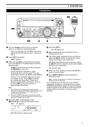
...Press to turn to step the operating frequency up or down {page 34}. Press and hold to enter split-frequency operation which allows you to use different transmission and reception frequencies {page 30}. #3 MULTI control In VFO mode, rotate to adjust the offset frequency. 3 GETTING ACQUAINTED #8#7 #6... HF/50MHz ALL MODE TRANSCEIVER TS-480 PF ANT 1/2 ATT/PRE AT AF SQL 1 REC 2 REC CH1 CH2 4 TX MONI 5 RF.G PWR MIC 7 8 NB/T VOX CLR 0 OFF ...
...Press to turn to step the operating frequency up or down {page 34}. Press and hold to enter split-frequency operation which allows you to use different transmission and reception frequencies {page 30}. #3 MULTI control In VFO mode, rotate to adjust the offset frequency. 3 GETTING ACQUAINTED #8#7 #6... HF/50MHz ALL MODE TRANSCEIVER TS-480 PF ANT 1/2 ATT/PRE AT AF SQL 1 REC 2 REC CH1 CH2 4 TX MONI 5 RF.G PWR MIC 7 8 NB/T VOX CLR 0 OFF ...

Operation Manual
Page 21
... 2 optional IF filters are installed and the transceiver selects the secondary IF filter, "NAR 2" appears {page 45}. !4 MHz Appears when the MHz Up/ Down mode using the MULTI control is ON {page 35}. !6 Appears when the selected Menu No. t PRE Appears when the receiver pre-amplifier (approx. 6 dB) is in the...
... 2 optional IF filters are installed and the transceiver selects the secondary IF filter, "NAR 2" appears {page 45}. !4 MHz Appears when the MHz Up/ Down mode using the MULTI control is ON {page 35}. !6 Appears when the selected Menu No. t PRE Appears when the receiver pre-amplifier (approx. 6 dB) is in the...

Operation Manual
Page 22
In Quick Memory mode, it is used to "9_") {page 55}. @7 Displays a communication mode {page 19}. @8 AUTO Appears when Auto Mode function is selected {pages 18, 30}. While the RIT, XIT or ...
In Quick Memory mode, it is used to "9_") {page 55}. @7 Displays a communication mode {page 19}. @8 AUTO Appears when Auto Mode function is selected {pages 18, 30}. While the RIT, XIT or ...

