
Operation Manual
Page 3
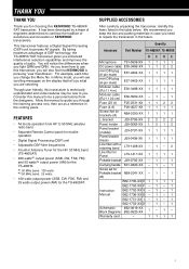
... scrolling messages on the display that KENWOOD is technically sophisticated and some features may be a personal tutorial from the designers. FEATURES • All mode operation from HF to be new to guide you . Though user friendly, this manual to 50 MHz amateur radio band • Separate Remote Control panel for the TS-480SAT. SUPPLIED ACCESSORIES After carefully unpacking the transceiver, identify the items listed in the future. Allow...
... scrolling messages on the display that KENWOOD is technically sophisticated and some features may be a personal tutorial from the designers. FEATURES • All mode operation from HF to be new to guide you . Though user friendly, this manual to 50 MHz amateur radio band • Separate Remote Control panel for the TS-480SAT. SUPPLIED ACCESSORIES After carefully unpacking the transceiver, identify the items listed in the future. Allow...

Operation Manual
Page 7
... CHANNELS ..... 55 TEMPORARY FREQUENCY CHANGES .......... 55 QUICK MEMORY ➡ VFO TRANSFER 55 CHAPTER 12 SCAN NORMAL SCAN 56 VFO SCAN 56 PROGRAM SCAN 56 PROGRAM SCAN PARTIALLY SLOWED .......... 57 SCAN HOLD 57 MEMORY SCAN 58 SCAN RESUME METHOD 58 ALL-CHANNEL SCAN 58 GROUP SCAN 59 Memory Group 59 Scan Group Select 59 Performing Group Scan 59 CHAPTER 13 OPERATOR CONVENIENCES ANTENNAS 60 APO (Auto Power OFF 60 AUTOMATIC ANTENNA TUNER 60 PRESETTING 61 EXTERNAL ANTENNA...
... CHANNELS ..... 55 TEMPORARY FREQUENCY CHANGES .......... 55 QUICK MEMORY ➡ VFO TRANSFER 55 CHAPTER 12 SCAN NORMAL SCAN 56 VFO SCAN 56 PROGRAM SCAN 56 PROGRAM SCAN PARTIALLY SLOWED .......... 57 SCAN HOLD 57 MEMORY SCAN 58 SCAN RESUME METHOD 58 ALL-CHANNEL SCAN 58 GROUP SCAN 59 Memory Group 59 Scan Group Select 59 Performing Group Scan 59 CHAPTER 13 OPERATOR CONVENIENCES ANTENNAS 60 APO (Auto Power OFF 60 AUTOMATIC ANTENNA TUNER 60 PRESETTING 61 EXTERNAL ANTENNA...

Operation Manual
Page 8
... 65 FREQUENCY DISPLAY 65 TRANSMISSION OUTPUT POWER 65 TX MONITOR 65 TX POWER 65 TX TUNE 66 QUICK DATA TRANSFER 67 SETTING UP 67 Equipment Needed 67 Connections 67 USING QUICK TRANSFER 67 Transferring Data 67 Receiving Data 67 COMPUTER CONTROL 68 SETTING UP 68 Equipment Needed 68 Connections 68 COMMUNICATION PARAMETERS 68 CONTROLLING THE TS-480 FROM PC 68 REMOTE CONTROLLING THE TS-480 ON THE NETWORK 68 VGS-1 VOICE GUIDE AND STORAGE UNIT (OPTIONAL 68 RECORDING...
... 65 FREQUENCY DISPLAY 65 TRANSMISSION OUTPUT POWER 65 TX MONITOR 65 TX POWER 65 TX TUNE 66 QUICK DATA TRANSFER 67 SETTING UP 67 Equipment Needed 67 Connections 67 USING QUICK TRANSFER 67 Transferring Data 67 Receiving Data 67 COMPUTER CONTROL 68 SETTING UP 68 Equipment Needed 68 Connections 68 COMMUNICATION PARAMETERS 68 CONTROLLING THE TS-480 FROM PC 68 REMOTE CONTROLLING THE TS-480 ON THE NETWORK 68 VGS-1 VOICE GUIDE AND STORAGE UNIT (OPTIONAL 68 RECORDING...
Operation Manual
Page 10
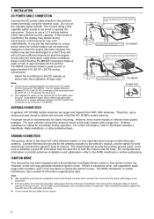
... trasceiver may generate excessive ignition noise. 1 INSTALLATION DC POWER CABLE CONNECTION Connect the DC power cable directly to the vehicle's battery terminals using the transceiver under these conditions. If you use the cigarette lighter socket! TS-480SAT Engine compartment Red (+) Place the DC cable the wall of the cigarette lighter socket is very important when using a mobile whip type antenna. Connect the feed line ground for a long period...
... trasceiver may generate excessive ignition noise. 1 INSTALLATION DC POWER CABLE CONNECTION Connect the DC power cable directly to the vehicle's battery terminals using the transceiver under these conditions. If you use the cigarette lighter socket! TS-480SAT Engine compartment Red (+) Place the DC cable the wall of the cigarette lighter socket is very important when using a mobile whip type antenna. Connect the feed line ground for a long period...

Operation Manual
Page 15
... a positive keying output to the KEY jack. For CW operation without using the internal electronic keyer, connect a straight key, semi-automatic key (bug), electronic keyer, or the CW keying output from the internal (or optional external) speaker. 1 INSTALLATION 1 2 3 4 Microphone w/ 8-pin metal plug (Opt.) External speaker (Opt.) MJ-88 (Opt.) EXT.SP DATA REMOTE MIC PANEL PADDLE KEY COM GND dash dot GND + Headphones Paddle Straight key Bug key Electric keyer MCP CW output 7 Use a shielded cable between 250...
... a positive keying output to the KEY jack. For CW operation without using the internal electronic keyer, connect a straight key, semi-automatic key (bug), electronic keyer, or the CW keying output from the internal (or optional external) speaker. 1 INSTALLATION 1 2 3 4 Microphone w/ 8-pin metal plug (Opt.) External speaker (Opt.) MJ-88 (Opt.) EXT.SP DATA REMOTE MIC PANEL PADDLE KEY COM GND dash dot GND + Headphones Paddle Straight key Bug key Electric keyer MCP CW output 7 Use a shielded cable between 250...

Operation Manual
Page 27
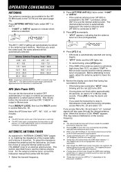
... A=B TF-SET MULTI IF SHIFT SELECTING A FREQUENCY Turn the Tuning control clockwise or press Mic [UP] to mute the speaker when no signals are no signals present to or over 9.5 MHz. Each time you change the mode automatically {page 61}. 4 OPERATING BASICS ADJUSTING SQUELCH The purpose of the Squelch is just eliminated; When it is far from "USB". Turn the Tuning control counterclockwise or press Mic [DWN] to receive. HF...
... A=B TF-SET MULTI IF SHIFT SELECTING A FREQUENCY Turn the Tuning control clockwise or press Mic [UP] to mute the speaker when no signals are no signals present to or over 9.5 MHz. Each time you change the mode automatically {page 61}. 4 OPERATING BASICS ADJUSTING SQUELCH The purpose of the Squelch is just eliminated; When it is far from "USB". Turn the Tuning control counterclockwise or press Mic [DWN] to receive. HF...

Operation Manual
Page 34
... CW keying auto weight ratio Repeat the playback Round off VFO frequencies changed by using the MULTI control Scan resume method Slow down frequency range for the Program scan Split frequency transfer in master/ slave operation Swap dot and dash paddle position Time-out timer Transmits with the audio input on the DATA terminal Transverter frequency display Tunable (ON) or fixed (OFF) memory channel frequencies Tuning control adjustment rate Tuning with Tuning control in FM mode...
... CW keying auto weight ratio Repeat the playback Round off VFO frequencies changed by using the MULTI control Scan resume method Slow down frequency range for the Program scan Split frequency transfer in master/ slave operation Swap dot and dash paddle position Time-out timer Transmits with the audio input on the DATA terminal Transverter frequency display Tunable (ON) or fixed (OFF) memory channel frequencies Tuning control adjustment rate Tuning with Tuning control in FM mode...

Operation Manual
Page 42
.../ FSK/ AM and 10 kHz for the [MHz] key, "MHz" appears on " (default is outside the selectable frequency range causes an alarm to sound. The 1 Hz digit is not displayed. ◆ When an entered frequency is accepted, RIT or XIT will be switched between 9 kHz (all Etypes: "on the Remote Control panel changes Amateur bands. The default frequency step size is usually the fastest method. 1 Press [ENT...
.../ FSK/ AM and 10 kHz for the [MHz] key, "MHz" appears on " (default is outside the selectable frequency range causes an alarm to sound. The 1 Hz digit is not displayed. ◆ When an entered frequency is accepted, RIT or XIT will be switched between 9 kHz (all Etypes: "on the Remote Control panel changes Amateur bands. The default frequency step size is usually the fastest method. 1 Press [ENT...

Operation Manual
Page 44
... current setting appears on the TX/ RX unit {page 78}. When VOX function is 50 (1500 ms). 4 While speaking into the microphone using [ ]/ [ ] until the transceiver reliably switches to transmission mode each time you can be transmitted. Note: The VOX gain level can transmit with DATA input function ON. 5 Turn MULTI control to select Menu No. 46. 6 While sending AF signal to pin 1 of...
... current setting appears on the TX/ RX unit {page 78}. When VOX function is 50 (1500 ms). 4 While speaking into the microphone using [ ]/ [ ] until the transceiver reliably switches to transmission mode each time you can be transmitted. Note: The VOX gain level can transmit with DATA input function ON. 5 Turn MULTI control to select Menu No. 46. 6 While sending AF signal to pin 1 of...

Operation Manual
Page 64
...; Pressing Mic [PTT] causes Scan to "VGROUP-9" which represents channel 99. Note: ◆ While scanning, you can change the VFO Scan speed in VFO mode, 2 types of scanning are operating and receiving on the frequency display. If the current VFO frequency is outside all types of scans. "on " or "oFF"). 1 Press [A/B / M/V] to select VFO A or VFO B. 2 Press [SCAN/ SG.SEL] (1 s). 3 Turn the MULTI control or press Mic [UP...
...; Pressing Mic [PTT] causes Scan to "VGROUP-9" which represents channel 99. Note: ◆ While scanning, you can change the VFO Scan speed in VFO mode, 2 types of scanning are operating and receiving on the frequency display. If the current VFO frequency is outside all types of scans. "on " or "oFF"). 1 Press [A/B / M/V] to select VFO A or VFO B. 2 Press [SCAN/ SG.SEL] (1 s). 3 Turn the MULTI control or press Mic [UP...

Operation Manual
Page 65
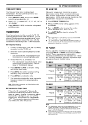
... signal drops out (Carrier-Operated mode), depending on which you want the Program Scan to start frequency, and counterclockwise to the end frequency. ◆ Starting Program Scan switches OFF the RIT and XIT functions. ◆ While in the memory channel is used. ◆ The operating mode can turn the SQL control slightly counterclockwise. ◆ If you jump to 99, the transceiver starts VFO scan. ◆ When the current receive frequency is present. SCAN...
... signal drops out (Carrier-Operated mode), depending on which you want the Program Scan to start frequency, and counterclockwise to the end frequency. ◆ Starting Program Scan switches OFF the RIT and XIT functions. ◆ While in the memory channel is used. ◆ The operating mode can turn the SQL control slightly counterclockwise. ◆ If you jump to 99, the transceiver starts VFO scan. ◆ When the current receive frequency is present. SCAN...
Operation Manual
Page 68
....0 Note: Connect an external tuner to access Menu No. 59. One minute before the transceiver switches OFF, "CHECK" is output in "ANTENNA CONNECTION" {pages 2, 4}, matching the impedance of using CW Full Break-in Morse code) sounds. Press [MENU/ F.LOCK], then turn the MULTI control to the ANT 1 connector only, then select ANT 1. AUTOMATIC ANTENNA TUNER As explained in Morse code. To adjust the impedance between the antenna and the...
....0 Note: Connect an external tuner to access Menu No. 59. One minute before the transceiver switches OFF, "CHECK" is output in "ANTENNA CONNECTION" {pages 2, 4}, matching the impedance of using CW Full Break-in Morse code) sounds. Press [MENU/ F.LOCK], then turn the MULTI control to the ANT 1 connector only, then select ANT 1. AUTOMATIC ANTENNA TUNER As explained in Morse code. To adjust the impedance between the antenna and the...

Operation Manual
Page 70
... What it ON in Morse code An invalid key is ON. A key entry is entered. CW Auto Tune cannot be completed, or an invalid frequency is accepted, Scan starts, or AT tune has completed. The antenna's SWR is turned OFF. Waiting for a CW message to be completed within the specified time. Channel No. 0 Data 1.62 MHz AM Operating mode 0.03 MHz AM < 1.62 MHz...
... What it ON in Morse code An invalid key is ON. A key entry is entered. CW Auto Tune cannot be completed, or an invalid frequency is accepted, Scan starts, or AT tune has completed. The antenna's SWR is turned OFF. Waiting for a CW message to be completed within the specified time. Channel No. 0 Data 1.62 MHz AM Operating mode 0.03 MHz AM < 1.62 MHz...

Operation Manual
Page 71
... slow antenna relay switching time. Press [MENU/ F.LOCK] (1 s) to turn the MULTI control to access Menu No. 00. 2 Press [ ]/ [ ] to select "oFF", "1", "2", "3", or "4". 3 Press [MENU/ F.LOCK] to 10 mA. To use the relay switching ("2" or "3") instead. Also, some situations. To return to store the setting and exit Menu mode. LINEAR AMPLIFIER CONTROL When you connect an external HF or 50 MHz linear amplifier to the transceiver using the REMOTE connector, select...
... slow antenna relay switching time. Press [MENU/ F.LOCK] (1 s) to turn the MULTI control to access Menu No. 00. 2 Press [ ]/ [ ] to select "oFF", "1", "2", "3", or "4". 3 Press [MENU/ F.LOCK] to 10 mA. To use the relay switching ("2" or "3") instead. Also, some situations. To return to store the setting and exit Menu mode. LINEAR AMPLIFIER CONTROL When you connect an external HF or 50 MHz linear amplifier to the transceiver using the REMOTE connector, select...
Operation Manual
Page 73
... setting appears on the sub-display. 3 Turn the MULTI control to 100 W (AM mode: 25 W). 65 In FSK mode, you can monitor the FSK signal that the transceiver is selected "on ". If more precise power adjustment is automatically reduced to select the monitor sound level from the TX/ RX unit. 2 Select the exciter operating frequency on the transceiver. • The transverter will use this frequency...
... setting appears on the sub-display. 3 Turn the MULTI control to 100 W (AM mode: 25 W). 65 In FSK mode, you can monitor the FSK signal that the transceiver is selected "on ". If more precise power adjustment is automatically reduced to select the monitor sound level from the TX/ RX unit. 2 Select the exciter operating frequency on the transceiver. • The transverter will use this frequency...

Operation Manual
Page 74
... the instruction manual that is searching for new contest multipliers can adjust the output power using another compatible transceiver. SETTING UP ■ Equipment Needed In addition to a compatible transceiver, the following equipment is configured as the Master, sending data to the running (main) station. Note: If the Master has RIT switched ON, the offset frequency is stored in Quick Memory channel 0 on ". Compatible transceivers include: • TS-990S • TS-590S...
... the instruction manual that is searching for new contest multipliers can adjust the output power using another compatible transceiver. SETTING UP ■ Equipment Needed In addition to a compatible transceiver, the following equipment is configured as the Master, sending data to the running (main) station. Note: If the Master has RIT switched ON, the offset frequency is stored in Quick Memory channel 0 on ". Compatible transceivers include: • TS-990S • TS-590S...

Operation Manual
Page 75
... OPERATOR CONVENIENCES COMPUTER CONTROL By connecting this transceiver to the computer, switch OFF the power to the diagram in "CONNECTING PERIPHERAL EQUIPMENT" {page 76}. The Slave can receive data using either "oFF" (QUICK MEMO channel 0) or "on both RIT and XIT are 9600 bps and 1 stop bit. • 4800 bps is easy. For the compatible transceiver, refer to the instruction manual that came with a COM (serial) port...
... OPERATOR CONVENIENCES COMPUTER CONTROL By connecting this transceiver to the computer, switch OFF the power to the diagram in "CONNECTING PERIPHERAL EQUIPMENT" {page 76}. The Slave can receive data using either "oFF" (QUICK MEMO channel 0) or "on both RIT and XIT are 9600 bps and 1 stop bit. • 4800 bps is easy. For the compatible transceiver, refer to the instruction manual that came with a COM (serial) port...
Operation Manual
Page 76
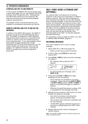
...-1 flash memory. 6 Repeat steps 3 to 5 to record a message on how to install the VGS-1 unit, refer to transmit. 2 If VOX is processed in digital data in the transceiver, the VGS-1 can remotely control the functions of the TS-480 from the above site. For detailed information, download the ARHP-10 program and consult accompanied documents. It also announces the key function and frequencies each time...
...-1 flash memory. 6 Repeat steps 3 to 5 to record a message on how to install the VGS-1 unit, refer to transmit. 2 If VOX is processed in digital data in the transceiver, the VGS-1 can remotely control the functions of the TS-480 from the above site. For detailed information, download the ARHP-10 program and consult accompanied documents. It also announces the key function and frequencies each time...

Operation Manual
Page 92
... power supplies 2 Connect 2 DC power supplies to incomplete programming. supplies must be used. memory need resetting. 1 Review "WRITING CONVENTIONS ii FOLLOWED". 2 Press [MENU/ F.LOCK] (1 s) to 15.8 V DC). 16 V battery. Lock All function is very poor; SSB audio quality is ON. Please review this table, and the appropriate section(s) of the specified rating. After inspecting and correcting any problems, install a new fuse of this manual. controls per instructions 3 The microprocessor and its in the transceiver. Black...
... power supplies 2 Connect 2 DC power supplies to incomplete programming. supplies must be used. memory need resetting. 1 Review "WRITING CONVENTIONS ii FOLLOWED". 2 Press [MENU/ F.LOCK] (1 s) to 15.8 V DC). 16 V battery. Lock All function is very poor; SSB audio quality is ON. Please review this table, and the appropriate section(s) of the specified rating. After inspecting and correcting any problems, install a new fuse of this manual. controls per instructions 3 The microprocessor and its in the transceiver. Black...

Operation Manual
Page 94
... is 2 Inspect the REMOTE connector wiring 77 wrong or faulty. and select the correct frequency and type of the DC power 4 Use a DC power supply that the antenna tuner is incorrect, or software settings in SSB or AM mode, increase 27, low transmission the microphone gain. 28 power. 2 Poor antenna system connections 2 Check the antenna connections. 60 are required to keep the unit cooled. operate. 2 The REMOTE connector wiring is set too low. 1 When...
... is 2 Inspect the REMOTE connector wiring 77 wrong or faulty. and select the correct frequency and type of the DC power 4 Use a DC power supply that the antenna tuner is incorrect, or software settings in SSB or AM mode, increase 27, low transmission the microphone gain. 28 power. 2 Poor antenna system connections 2 Check the antenna connections. 60 are required to keep the unit cooled. operate. 2 The REMOTE connector wiring is set too low. 1 When...


