Instruction Manual
Page 1
... instruction manual. Familiarity with installation and operation procedures will help you call upon your Kenwood product at www.kenwoodusa.com © B64-3925-00/00 (KV/EV) Model KAC-9104D Serial number US Residence Only Register Online Register your Kenwood dealer for information or service on the warranty card, and in the spaces designated on the product. KAC-9104D CLASS D MONO POWER AMPLIFIER 7 page 2-5 INSTRUCTION MANUAL AMPLIFICATEUR MONO CLASSE D 7 page 6-9 MODE D'EMPLOI AMPLIFICADOR...
... instruction manual. Familiarity with installation and operation procedures will help you call upon your Kenwood product at www.kenwoodusa.com © B64-3925-00/00 (KV/EV) Model KAC-9104D Serial number US Residence Only Register Online Register your Kenwood dealer for information or service on the warranty card, and in the spaces designated on the product. KAC-9104D CLASS D MONO POWER AMPLIFIER 7 page 2-5 INSTRUCTION MANUAL AMPLIFICATEUR MONO CLASSE D 7 page 6-9 MODE D'EMPLOI AMPLIFICADOR...
Instruction Manual
Page 2
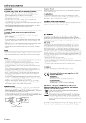
... the power cord and ground, use a power supply wiring wire and protective fuse of handling these items and their waste byproducts. Old electrical and electronic equipment should be working right, consult your local authority for details in the instruction manual. NOTE This Class B digital apparatus complies with the prescribed rating. Use it can be determined by turning the equipment off and on, the user is not connected. •...
... the power cord and ground, use a power supply wiring wire and protective fuse of handling these items and their waste byproducts. Old electrical and electronic equipment should be working right, consult your local authority for details in the instruction manual. NOTE This Class B digital apparatus complies with the prescribed rating. Use it can be determined by turning the equipment off and on, the user is not connected. •...
Instruction Manual
Page 3
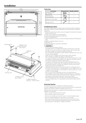
... the battery to prevent short circuits. 2.Set the unit according to the intended usage. 3.Connect the input and output wires of the units. 4.Connect the speaker wires. 5.Connect the power wire, power control wire and grounding wire following situations: This unit is nothing hazardous on top of the unit. • The surface temperature of the amplifier will not obstruct driving. Blocking these openings will not come into contact with a protection function for protecting this order. 6.Install the installation...
... the battery to prevent short circuits. 2.Set the unit according to the intended usage. 3.Connect the input and output wires of the units. 4.Connect the speaker wires. 5.Connect the power wire, power control wire and grounding wire following situations: This unit is nothing hazardous on top of the unit. • The surface temperature of the amplifier will not obstruct driving. Blocking these openings will not come into contact with a protection function for protecting this order. 6.Install the installation...
Instruction Manual
Page 4
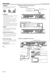
... Speaker level input connection • RCA cable connections CENTER UNIT (CD receiver, etc.) * Commercially available parts Power control wire RCA cable* 2CAUTION • If sound is not output normally, immediately turn power off and check connections. • Be sure to turn the power off as the unit detects input signal (Signal Sensing Turn-ON). Do not remove caps from the line input terminal is output. 30 30 Fuse 30 A × 2 Lead terminal* Terminal cover Subwoofer (L + R) (≥1Ω) Battery wire* Protective Fuse* When two subwoofers are touching the car...
... Speaker level input connection • RCA cable connections CENTER UNIT (CD receiver, etc.) * Commercially available parts Power control wire RCA cable* 2CAUTION • If sound is not output normally, immediately turn power off and check connections. • Be sure to turn the power off as the unit detects input signal (Signal Sensing Turn-ON). Do not remove caps from the line input terminal is output. 30 30 Fuse 30 A × 2 Lead terminal* Terminal cover Subwoofer (L + R) (≥1Ω) Battery wire* Protective Fuse* When two subwoofers are touching the car...
Instruction Manual
Page 5
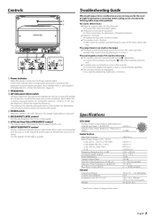
...; of the terminals and wires well. ✔ A speaker wire is reversed. 5 BASS BOOST LEVEL control Sets the low frequency level to be compensated. 6 LPF(Low-Pass Filter) FREQUENCY control This control adjusts the frequency band output from this unit. 7 INPUT SENSITIVITY control Set this control according to . Setting this unit, or to the maximum power output of the speakers by eliminating unnecessary oscillations which affect the sound by referring to the pre-output level of slight misoperation or miswiring. Troubleshooting Guide What might appear...
...; of the terminals and wires well. ✔ A speaker wire is reversed. 5 BASS BOOST LEVEL control Sets the low frequency level to be compensated. 6 LPF(Low-Pass Filter) FREQUENCY control This control adjusts the frequency band output from this unit. 7 INPUT SENSITIVITY control Set this control according to . Setting this unit, or to the maximum power output of the speakers by eliminating unnecessary oscillations which affect the sound by referring to the pre-output level of slight misoperation or miswiring. Troubleshooting Guide What might appear...


