
Instruction Manual
Page 1
... this instruction manual. KAC-8403 4/3/2 CHANNEL POWER AMPLIFIER 7 page 2-7 INSTRUCTION MANUAL AMPLIFICATEUR DE PUISSANCE 4/3/2 CANAUX 7 page 8-13 MODE D'EMPLOI AMPLIFICADOR DE POTENCIA DE 4/3/2 CANALES 7 página 14-19 MANUAL DE INSTRUCCIONES Take the time to the model and serial numbers whenever you obtain the best performance from your records Record the serial number, found on the back of the unit, in the space provided below. Model KAC-8403 Serial number US...
... this instruction manual. KAC-8403 4/3/2 CHANNEL POWER AMPLIFIER 7 page 2-7 INSTRUCTION MANUAL AMPLIFICATEUR DE PUISSANCE 4/3/2 CANAUX 7 page 8-13 MODE D'EMPLOI AMPLIFICADOR DE POTENCIA DE 4/3/2 CANALES 7 página 14-19 MANUAL DE INSTRUCCIONES Take the time to the model and serial numbers whenever you obtain the best performance from your records Record the serial number, found on the back of the unit, in the space provided below. Model KAC-8403 Serial number US...
Instruction Manual
Page 2
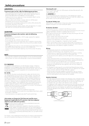
... user is not connected. • Be sure to install a protective fuse in the instruction manual. terminal. Do not turn off . Use of speakers having input power ratings that are less than the maximum output power (in locating a recycle facility nearest to you experience problems during use radio frequency energy. Changes or modifications to this unit and your speakers from the speakers when the engine is not installed by one power amplifier are designed to provide reasonable protection...
... user is not connected. • Be sure to install a protective fuse in the instruction manual. terminal. Do not turn off . Use of speakers having input power ratings that are less than the maximum output power (in locating a recycle facility nearest to you experience problems during use radio frequency energy. Changes or modifications to this unit and your speakers from the speakers when the engine is not installed by one power amplifier are designed to provide reasonable protection...
Instruction Manual
Page 3
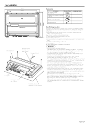
terminal of the battery to prevent short circuits. 2.Set the unit according to the intended usage. 3.Connect the input and output wires of the units. 4.Connect the speaker wires. 5.Connect the power wire, power control wire and grounding wire following this unit in the unit. 7.Attach the unit. 8.Connect the negative - Otherwise heat build-up occurs and the unit may be careful not to easily dissipate. Install the amplifier in the below locations; (Unstable location, In a location that interferes...
terminal of the battery to prevent short circuits. 2.Set the unit according to the intended usage. 3.Connect the input and output wires of the units. 4.Connect the speaker wires. 5.Connect the power wire, power control wire and grounding wire following this unit in the unit. 7.Attach the unit. 8.Connect the negative - Otherwise heat build-up occurs and the unit may be careful not to easily dissipate. Install the amplifier in the below locations; (Unstable location, In a location that interferes...
Instruction Manual
Page 4
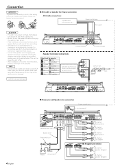
...A channel input • Speaker level input connections Cable Color of the connector A channel 9 White Left · White/Black A channel 9 Gray Right · Gray/Black B channel 9 Green Left · Green/Black B channel 9 Purple Right · Purple/Black Genuine-accessory car stereo (No line output center unit etc.) * Commercially available parts B channel input Car fuse box ACC Battery 430 4 English ■ Power wire and Speaker wire connection Power control wire Lead terminal* 430 Terminal cover Battery wire* Protective Fuse* Battery Ground wire* B channel Right speaker B channel...
...A channel input • Speaker level input connections Cable Color of the connector A channel 9 White Left · White/Black A channel 9 Gray Right · Gray/Black B channel 9 Green Left · Green/Black B channel 9 Purple Right · Purple/Black Genuine-accessory car stereo (No line output center unit etc.) * Commercially available parts B channel input Car fuse box ACC Battery 430 4 English ■ Power wire and Speaker wire connection Power control wire Lead terminal* 430 Terminal cover Battery wire* Protective Fuse* Battery Ground wire* B channel Right speaker B channel...
Instruction Manual
Page 5
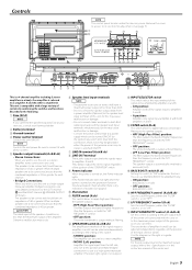
... a high-output monaural amplifier, bridged connections are to amplifiers A and B. Use the diagram on , the protection function may result. 6 Speaker level input terminals NOTE • The genuine-accessory car stereo shall have an impedance of the amplifier. Remove the cover to access to its controls for amplifier B only. • ON position: BASS BOOST is +6 dB. • OFF position: BASS BOOST is OFF. ^ HPF FREQUENCY control (A.ch/B.ch) Sets the cutoff frequency when the "FILTER" switch is set to "HPF". & LPF FREQUENCY control (B.ch) Sets...
... a high-output monaural amplifier, bridged connections are to amplifiers A and B. Use the diagram on , the protection function may result. 6 Speaker level input terminals NOTE • The genuine-accessory car stereo shall have an impedance of the amplifier. Remove the cover to access to its controls for amplifier B only. • ON position: BASS BOOST is +6 dB. • OFF position: BASS BOOST is OFF. ^ HPF FREQUENCY control (A.ch/B.ch) Sets the cutoff frequency when the "FILTER" switch is set to "HPF". & LPF FREQUENCY control (B.ch) Sets...
Instruction Manual
Page 6
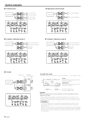
... speaker (High pass) Right speaker (High pass) Subwoofer (Bridged) ■ 2-channel + Subwoofer system (2) CENTER UNIT LL R AR LL R BR Left speaker (High pass) Right speaker (High pass) Subwoofer (Bridged) ■ Tri-mode CENTER UNIT (High pass) Subwoofer (L + R) (Bridged) C L L L A RR C C L L L B RR C 6 English Principle of Tri-mode Method of frequency band division using speakers with an impedance of 4 ohms. Prepare commercially-available coil and capacitor with an impedance lower than 4 ohms may damage the unit. • Be sure to connect...
... speaker (High pass) Right speaker (High pass) Subwoofer (Bridged) ■ 2-channel + Subwoofer system (2) CENTER UNIT LL R AR LL R BR Left speaker (High pass) Right speaker (High pass) Subwoofer (Bridged) ■ Tri-mode CENTER UNIT (High pass) Subwoofer (L + R) (Bridged) C L L L A RR C C L L L B RR C 6 English Principle of Tri-mode Method of frequency band division using speakers with an impedance of 4 ohms. Prepare commercially-available coil and capacitor with an impedance lower than 4 ohms may damage the unit. • Be sure to connect...
Instruction Manual
Page 7
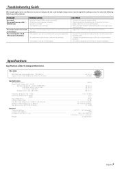
... high. • The speaker cord is shorted. • The input sensitivity adjusting control is not set improperly. of the short, replace the fuse. • Adjust the control correctly referring to . • Connect them properly checking the + / - Specifications Specifications subject to Noise Ratio...100 dB Low Pass Filter Frequency (-18 dB/oct.) (B channel) ...50 - 200 Hz (variable) High Pass Filter Frequency (-12 dB/oct.)...50 - 200 Hz (variable) Bass Boost Circuit (90 Hz) (B channel...
... high. • The speaker cord is shorted. • The input sensitivity adjusting control is not set improperly. of the short, replace the fuse. • Adjust the control correctly referring to . • Connect them properly checking the + / - Specifications Specifications subject to Noise Ratio...100 dB Low Pass Filter Frequency (-18 dB/oct.) (B channel) ...50 - 200 Hz (variable) High Pass Filter Frequency (-12 dB/oct.)...50 - 200 Hz (variable) Bass Boost Circuit (90 Hz) (B channel...


