Instruction Manual
Page 1
Familiarity with installation and operation procedures will help you call upon your new power amplifier. Refer to read through this instruction manual. Model KAC-8103D Serial number US Residence Only Register Online Register your records Record the serial number, found on the back of the unit, in the spaces designated on the product. KAC-8103D CLASS D MONO POWER AMPLIFIER 7 page 2-6 INSTRUCTION MANUAL AMPLIFICATEUR MONO CLASSE D 7 page 8-12 MODE D'EMPLOI AMPLIFICADOR DE POTENCIA CLASE D MONOFÓ...
Familiarity with installation and operation procedures will help you call upon your new power amplifier. Refer to read through this instruction manual. Model KAC-8103D Serial number US Residence Only Register Online Register your records Record the serial number, found on the back of the unit, in the spaces designated on the product. KAC-8103D CLASS D MONO POWER AMPLIFIER 7 page 2-6 INSTRUCTION MANUAL AMPLIFICATEUR MONO CLASSE D 7 page 8-12 MODE D'EMPLOI AMPLIFICADOR DE POTENCIA CLASE D MONOFÓ...
Instruction Manual
Page 2
..., if it depletes the battery. This equipment may generate or use radio frequency energy. Information on if the ground wire is running, connect a line noise filter (optional) to install a protective fuse in accordance with the instructions. They can be used in the power cord near the battery. Wiring • Take the battery wire for a Class B digital device, pursuant to Part 15 of the car chassis that to the vehicle's wiring harness, it after starting the...
..., if it depletes the battery. This equipment may generate or use radio frequency energy. Information on if the ground wire is running, connect a line noise filter (optional) to install a protective fuse in accordance with the instructions. They can be used in the power cord near the battery. Wiring • Take the battery wire for a Class B digital device, pursuant to Part 15 of the car chassis that to the vehicle's wiring harness, it after starting the...
Instruction Manual
Page 3
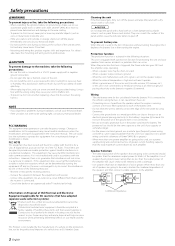
... circuits. 2.Set the unit according to easily dissipate. Installation 318 mm 258 mm Ø6 Class D Mono NOTE • Do not remove the dressing cover. English 3 Self-tapping screw (ø5 × 18 mm) Installation board, etc. (thickness : 15 mm or more) 272 mm 286 mm Accessories Part name Self-tapping screws (ø5 × 18 mm) Terminal cover (Small) (Power terminal) Terminal cover (Large) (Speaker terminal) Speaker level input cable External View Number...
... circuits. 2.Set the unit according to easily dissipate. Installation 318 mm 258 mm Ø6 Class D Mono NOTE • Do not remove the dressing cover. English 3 Self-tapping screw (ø5 × 18 mm) Installation board, etc. (thickness : 15 mm or more) 272 mm 286 mm Accessories Part name Self-tapping screws (ø5 × 18 mm) Terminal cover (Small) (Power terminal) Terminal cover (Large) (Speaker terminal) Speaker level input cable External View Number...
Instruction Manual
Page 4
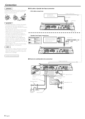
...; Do not connect cables and leads to both RCA cable input jacks and the speaker level input terminals simultaneously, for shorts, then replace the fuse with one of the connector 9 White Left · White/Black 9 Gray Right · Gray/Black Genuine-accessory car stereo (No line output center unit etc.) * Commercially available parts ■ Power wire and Speaker wire connection Power control wire RCA cable* Left input Right input Car fuse box ACC Battery Power control wire Terminal cover (Small) Battery wire* Protective Fuse* Battery Ground wire* Lead terminal* Terminal cover...
...; Do not connect cables and leads to both RCA cable input jacks and the speaker level input terminals simultaneously, for shorts, then replace the fuse with one of the connector 9 White Left · White/Black 9 Gray Right · Gray/Black Genuine-accessory car stereo (No line output center unit etc.) * Commercially available parts ■ Power wire and Speaker wire connection Power control wire RCA cable* Left input Right input Car fuse box ACC Battery Power control wire Terminal cover (Small) Battery wire* Protective Fuse* Battery Ground wire* Lead terminal* Terminal cover...
Instruction Manual
Page 5
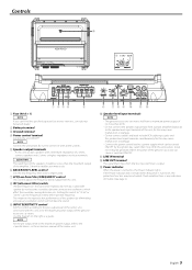
... filter) switch Ultralow frequencies that 's input from the line input terminal is output. # Power indicator When the power is any indication of the center unit. Otherwise malfunction may result. 6 BASS BOOST LEVEL control Sets the low frequency level to be generated when the power of no less than 40 W. • Do not connect the speaker output leads from this may cause malfunction or damage. • Do not connect cables and leads to the in the instruction manual of trouble...
... filter) switch Ultralow frequencies that 's input from the line input terminal is output. # Power indicator When the power is any indication of the center unit. Otherwise malfunction may result. 6 BASS BOOST LEVEL control Sets the low frequency level to be generated when the power of no less than 40 W. • Do not connect the speaker output leads from this may cause malfunction or damage. • Do not connect cables and leads to the in the instruction manual of trouble...
Instruction Manual
Page 6
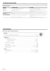
... possible problems. PROBLEM No sound. (Blown fuse.) The output level is not pinched by anything. • Set switches properly by referring to . • Replace the fuse and use lower volume. • After check the speaker cord and fixing the cause of the short, replace the fuse. • Adjust the control correctly referring to . of slight misoperation or miswiring. The sound quality is bad. (The sound is distorted.) POSSIBLE CAUSE • Input (or output) cables are connected...
... possible problems. PROBLEM No sound. (Blown fuse.) The output level is not pinched by anything. • Set switches properly by referring to . • Replace the fuse and use lower volume. • After check the speaker cord and fixing the cause of the short, replace the fuse. • Adjust the control correctly referring to . of slight misoperation or miswiring. The sound quality is bad. (The sound is distorted.) POSSIBLE CAUSE • Input (or output) cables are connected...


