
Installation Instructions
Page 1
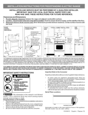
...the floor. 3. IMPORTANT: SAVE FOR LOCAL ELECTRICAL INSPECTOR'S USE. Clearances and Dimensions 1. Be sure your owner'sguide for models equipped withstorage drawers Fig. 2 Fig. :3 ,t_ 30" -_ 0" clearancebelow cookingtop and at rear of range. *30" MINIMUM CLEARANCE BETWEEN THE TOP OF THE COOKING... to the Installer Read all instructions contained in the Use & Care Guide, read it carefully. Check for proper electrical supply, and the stability of range _®'® 1[_ _ above the elements should follow. Important Notes to reach over the surface elements, cabinet ...
...the floor. 3. IMPORTANT: SAVE FOR LOCAL ELECTRICAL INSPECTOR'S USE. Clearances and Dimensions 1. Be sure your owner'sguide for models equipped withstorage drawers Fig. 2 Fig. :3 ,t_ 30" -_ 0" clearancebelow cookingtop and at rear of range. *30" MINIMUM CLEARANCE BETWEEN THE TOP OF THE COOKING... to the Installer Read all instructions contained in the Use & Care Guide, read it carefully. Check for proper electrical supply, and the stability of range _®'® 1[_ _ above the elements should follow. Important Notes to reach over the surface elements, cabinet ...
Installation Instructions
Page 2
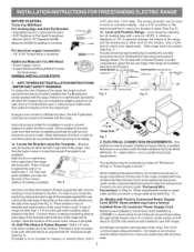
... Warmer Drawer or broiler compartment, grasp the top rear edge of the screw holes, shown in Step 4c. If range is to be replaced properly and could create a potential electrical hazard if wires become pinched. Use the information below to masonry or ceramic floors, drill a 3/16" pilot hole... 125/250 volts minimum and marked for the bracket. Locate the Bracket using flexible conduit or range cable use with a wrench. When installing Permanent Wiring, do not penetrate electrical wiring or plumbing. Failure to install the anti-tip bracket will allow room for use flex ...
... Warmer Drawer or broiler compartment, grasp the top rear edge of the screw holes, shown in Step 4c. If range is to be replaced properly and could create a potential electrical hazard if wires become pinched. Use the information below to masonry or ceramic floors, drill a 3/16" pilot hole... 125/250 volts minimum and marked for the bracket. Locate the Bracket using flexible conduit or range cable use with a wrench. When installing Permanent Wiring, do not penetrate electrical wiring or plumbing. Failure to install the anti-tip bracket will allow room for use flex ...
Installation Instructions
Page 3
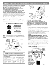
... NOT LOOSEN the factory installed nut connections which secure the range wiring to Fig.12) Before wiring the range review the suggested power source location drawing in . Make sure all screws are loosened or removed. 3. ELECTRICAL CONNECTION TO RANGE. To remove, loosen center screw (one screw) and ... 1-3/8" dia. Cord must disconnect the ground strap. 2b. MODELS REQUIRING POWER SUPPLY CORD KIT. RISK OF FIRE OR ELECTRICAL SHOCK MAY OCCUR IFAN INCORRECT SIZE RANGE CORD KIT IS USED, THE INSTALLATION INSTRUCTIONS ARE NOT FOLLOWED OR STRAIN RELIEF BRACKETIS DISCARDED. Fig. 10 f .... Cut...
... NOT LOOSEN the factory installed nut connections which secure the range wiring to Fig.12) Before wiring the range review the suggested power source location drawing in . Make sure all screws are loosened or removed. 3. ELECTRICAL CONNECTION TO RANGE. To remove, loosen center screw (one screw) and ... 1-3/8" dia. Cord must disconnect the ground strap. 2b. MODELS REQUIRING POWER SUPPLY CORD KIT. RISK OF FIRE OR ELECTRICAL SHOCK MAY OCCUR IFAN INCORRECT SIZE RANGE CORD KIT IS USED, THE INSTALLATION INSTRUCTIONS ARE NOT FOLLOWED OR STRAIN RELIEF BRACKETIS DISCARDED. Fig. 10 f .... Cut...
Installation Instructions
Page 4
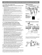
...is installed on block Connect line 2 hem Fig. 13 FOR 3 & 4-Wire Permanent Connections - follow Steps 1,2 & 5 below . Electrical failure or loss of the range. 4 3-Wire Connection CoRRect line 1 Terminal block 3 Factory installed connections (DO NOT LOOSEN) Connect neutral center) here Ground strap Ground ..._CONNECTION GROUND WIRELEAD Fig. 15 IMPORTANT NOTE: DO NOT LOOSEN the factory installed nut connections which secure the range wiring to check the level of electrical connection may occur if these 3 nuts are tightened securely and replace the rear access cover (See Fig. ...
...is installed on block Connect line 2 hem Fig. 13 FOR 3 & 4-Wire Permanent Connections - follow Steps 1,2 & 5 below . Electrical failure or loss of the range. 4 3-Wire Connection CoRRect line 1 Terminal block 3 Factory installed connections (DO NOT LOOSEN) Connect neutral center) here Ground strap Ground ..._CONNECTION GROUND WIRELEAD Fig. 15 IMPORTANT NOTE: DO NOT LOOSEN the factory installed nut connections which secure the range wiring to check the level of electrical connection may occur if these 3 nuts are tightened securely and replace the rear access cover (See Fig. ...


