Operation Manual
Page 6
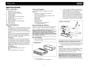
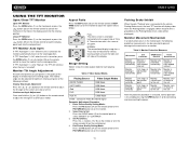
... other tools) • Electrical tape • Crimping tool • Volt meter/test light • Crimp connections • 18 gauge wire for VM9312HD 4. Press the metal levers on both sides to make the unit more stable. Install adapter if necessary (optional). c. With the sleeve ...and operating properly, the CAMERA source mode will become active. Under these tools and supplies to install your VM9312HD: • Torx type, flat-head and Philips screwdrivers • Wire cutters and strippers • Tools to installation. Pre-installation 1. Install the half-sleeve. a. b. ...
... other tools) • Electrical tape • Crimping tool • Volt meter/test light • Crimp connections • 18 gauge wire for VM9312HD 4. Press the metal levers on both sides to make the unit more stable. Install adapter if necessary (optional). c. With the sleeve ...and operating properly, the CAMERA source mode will become active. Under these tools and supplies to install your VM9312HD: • Torx type, flat-head and Philips screwdrivers • Wire cutters and strippers • Tools to installation. Pre-installation 1. Install the half-sleeve. a. b. ...
Operation Manual
Page 7
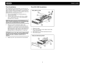
...DVD player, the chassis must be on new radio using existing screws from old radio. 3. Slide radio chassis into place. Reinstall dash panel. FINAL ISO-DIN INSTALLATION 3 BAND AS/PS PRELOSS/DAXUDIO VM9312 SRC DISP OPEN EJECT MUTE 4 1 2 3 VM9312HD Make sure the unit is achieved, turn the unit on to existing wiring...to a secure part of the dashboard either above or below the radio using the screw and hex nut provided. Connect wiring adapter to confirm operation (ignition switch must be supported with final mounting of the chassis. 1. Replace any items you removed from ...
...DVD player, the chassis must be on new radio using existing screws from old radio. 3. Slide radio chassis into place. Reinstall dash panel. FINAL ISO-DIN INSTALLATION 3 BAND AS/PS PRELOSS/DAXUDIO VM9312 SRC DISP OPEN EJECT MUTE 4 1 2 3 VM9312HD Make sure the unit is achieved, turn the unit on to existing wiring...to a secure part of the dashboard either above or below the radio using the screw and hex nut provided. Connect wiring adapter to confirm operation (ignition switch must be supported with final mounting of the chassis. 1. Replace any items you removed from ...
Operation Manual
Page 8
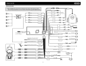
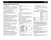
REAR R+ REAR R- GREEN + REAR L GREEN/BLACK - REAR L+ REAR L- VM9312HD WIRING DIAGRAM * See the Module Connections diagram for more information about connecting a satellite receiver and an iPod (through the MediaLink). FRONT R+ FRONT R- WHITE + FRONT L WHITE/BLACK - ...
REAR R+ REAR R- GREEN + REAR L GREEN/BLACK - REAR L+ REAR L- VM9312HD WIRING DIAGRAM * See the Module Connections diagram for more information about connecting a satellite receiver and an iPod (through the MediaLink). FRONT R+ FRONT R- WHITE + FRONT L WHITE/BLACK - ...
Operation Manual
Page 15
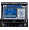
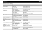
...DVD RGB Mode AUX IN CVBS Mode *CVBS - Set Parameters: Press the +/- swivels back els back to to the unit the unit After the protective procedure is executed, normal operation is the same at any point. VM9312HD USING THE TFT MONITOR Open/Close TFT Monitor Open TFT Monitor... automatically loaded into unit Monitor Unit stops at loading in obstruction horizontally point Monitor loading out vertically Monitor loading in relationship to 9. TFT Monitor Auto Open If "TFT Auto Open" is "on the monitor Parking Brake Inhibit When the pink "Parking" wire is connected to the ...
...DVD RGB Mode AUX IN CVBS Mode *CVBS - Set Parameters: Press the +/- swivels back els back to to the unit the unit After the protective procedure is executed, normal operation is the same at any point. VM9312HD USING THE TFT MONITOR Open/Close TFT Monitor Open TFT Monitor... automatically loaded into unit Monitor Unit stops at loading in obstruction horizontally point Monitor loading out vertically Monitor loading in relationship to 9. TFT Monitor Auto Open If "TFT Auto Open" is "on the monitor Parking Brake Inhibit When the pink "Parking" wire is connected to the ...
Operation Manual
Page 16
... 8) is held down and function 5 is compatible with the PAC adapter for detailed installation information. +14 - 0- Steering Wheel Control (SWC) The VM9312HD is pressed momentarily, Preset Down will be available on the remote control, or use the joystick to highlight the audio feature to be disabled through... to easily adjust your audio system to change between available playing sources in the LCD (7). Touch the screen or press the joystick button (13) to power off the unit.The monitor is displayed on the remote to meet the acoustical characteristics of your vehicle, which...
... 8) is held down and function 5 is compatible with the PAC adapter for detailed installation information. +14 - 0- Steering Wheel Control (SWC) The VM9312HD is pressed momentarily, Preset Down will be available on the remote control, or use the joystick to highlight the audio feature to be disabled through... to easily adjust your audio system to change between available playing sources in the LCD (7). Touch the screen or press the joystick button (13) to power off the unit.The monitor is displayed on the remote to meet the acoustical characteristics of your vehicle, which...
Operation Manual
Page 30
VM9312HD TROUBLESHOOTING Problem GENERAL Unit will not power on Remote control does not function No/low audio output Poor sound quality or distortion Tel-Mute malfunction Unit resets itself when engine is off TFT MONITOR Monitor...positive Check wiring and correct battery wire TFT Auto Open is turned off Incorrect connection to parking brake wire PRK SW is activated and parking brake is not engaged DVD is not...parking brake Change setup to accommodate disc Check wiring and correct Use correct aspect ratio setting Press OPEN key to restart monitor movement Auto antenna is not fully extended Auto...
VM9312HD TROUBLESHOOTING Problem GENERAL Unit will not power on Remote control does not function No/low audio output Poor sound quality or distortion Tel-Mute malfunction Unit resets itself when engine is off TFT MONITOR Monitor...positive Check wiring and correct battery wire TFT Auto Open is turned off Incorrect connection to parking brake wire PRK SW is activated and parking brake is not engaged DVD is not...parking brake Change setup to accommodate disc Check wiring and correct Use correct aspect ratio setting Press OPEN key to restart monitor movement Auto antenna is not fully extended Auto...
Quick Start Guide
Page 1
... R+ FRONT RREAR R+ REAR RREAR L+ REAR L- NeFeodr theechlpn?ical Faosrstiesctahnncicea, lcall asstihsteaAncued,iocvaollx thecJuesntosmener scuupsptoomrtelirne at s1u-p8p0o0r-t3l2in3e-4a8t 15. 1-800-323- 4815. Follow the wiring instructions carefully, or have the installation handled by an experienced technician. External Power Amplifier SUB.W REAR R REAR L FRONT R * See other side for more information about...
... R+ FRONT RREAR R+ REAR RREAR L+ REAR L- NeFeodr theechlpn?ical Faosrstiesctahnncicea, lcall asstihsteaAncued,iocvaollx thecJuesntosmener scuupsptoomrtelirne at s1u-p8p0o0r-t3l2in3e-4a8t 15. 1-800-323- 4815. Follow the wiring instructions carefully, or have the installation handled by an experienced technician. External Power Amplifier SUB.W REAR R REAR L FRONT R * See other side for more information about...

Quick Start Guide
Page 2
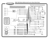
CNP2000UC 3. iPod Touch, iPod Classic and iPod Nano with video will only play music files. *** Printed in China XMD1000 (requires XMC or XMDJEN100 Cable Kit) 2. HD MODULE Compatible SAT Tuners: 1. SC-C1 and SIRJEN2 *** Requires Gen 5.5 or earlier photo or video iPod. VM9312HD Mobile Multimedia Receiver Quick Start Guide Wiring Example for MediaLink (iPods and SAT Equipment Sold Separately) NOTE: See other side for overall wiring diagram.
CNP2000UC 3. iPod Touch, iPod Classic and iPod Nano with video will only play music files. *** Printed in China XMD1000 (requires XMC or XMDJEN100 Cable Kit) 2. HD MODULE Compatible SAT Tuners: 1. SC-C1 and SIRJEN2 *** Requires Gen 5.5 or earlier photo or video iPod. VM9312HD Mobile Multimedia Receiver Quick Start Guide Wiring Example for MediaLink (iPods and SAT Equipment Sold Separately) NOTE: See other side for overall wiring diagram.


