
User Manual
Page 6
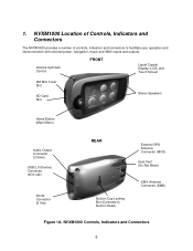
1. NVXM1000 Controls, Indicators and Connectors 5 Volume Up/Down Control FRONT Liquid Crystal Display (LCD) and Touch Screen XM Mini-Tuner Slot SD Card Slot Stereo Speakers Home Button (Main Menu) Audio Output Connector (3.5mm) USB 2.0 (Device) Connector (mini-usb) DC IN Connector (5 Vdc) REAR External GPS Antenna Connector (MCX) Heat Vent (Do Not Block) Suction Cup Locking...
1. NVXM1000 Controls, Indicators and Connectors 5 Volume Up/Down Control FRONT Liquid Crystal Display (LCD) and Touch Screen XM Mini-Tuner Slot SD Card Slot Stereo Speakers Home Button (Main Menu) Audio Output Connector (3.5mm) USB 2.0 (Device) Connector (mini-usb) DC IN Connector (5 Vdc) REAR External GPS Antenna Connector (MCX) Heat Vent (Do Not Block) Suction Cup Locking...

User Manual
Page 8
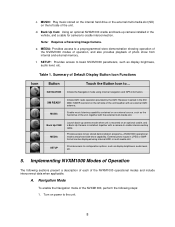
Figure 3. NAVIGATION: Using GPS information and preprogrammed navigation information. If the NVXM1000 was recently on the unit and the operational modes default display appears. Figure 2. Modes of the unit, with the external XM antenna attached. 7 Operational Modes Default Display 4. Jensen Logo at Power On e. b. XM® READY: Using the Mini XM® Tuner, installed in the XM MINI TUNER slot on the...
Figure 3. NAVIGATION: Using GPS information and preprogrammed navigation information. If the NVXM1000 was recently on the unit and the operational modes default display appears. Figure 2. Modes of the unit, with the external XM antenna attached. 7 Operational Modes Default Display 4. Jensen Logo at Power On e. b. XM® READY: Using the Mini XM® Tuner, installed in the XM MINI TUNER slot on the...
User Manual
Page 9
... Navigation Mode To enable the Navigation mode of the NVXM1000, perform the following sections present a description of each of the unit. XM READY MUSIC Initiate XM® radio operation provided by the XM® Receiver inserted in JPEG or BMP format can be displayed...GPS information. c. Back Up Cam: Using an optional NVXM1000 cradle and back-up camera mode when unit is mounted on the left side of the NVXM1000 operational modes and include interconnect data when applicable. MEDIA: Provides access to -cradle interconnecting cable. f. External photo inputs in the XM MINI-TUNER...
... Navigation Mode To enable the Navigation mode of the NVXM1000, perform the following sections present a description of each of the unit. XM READY MUSIC Initiate XM® radio operation provided by the XM® Receiver inserted in JPEG or BMP format can be displayed...GPS information. c. Back Up Cam: Using an optional NVXM1000 cradle and back-up camera mode when unit is mounted on the left side of the NVXM1000 operational modes and include interconnect data when applicable. MEDIA: Provides access to -cradle interconnecting cable. f. External photo inputs in the XM MINI-TUNER...
User Manual
Page 10
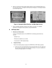
A navigation warning screen will appear on the LCD touch screen. Equipment Setup Perform the following optional items are required: • XM Mini-Tuner • XM antenna installed in your vehicle. • A subscription to prepare the NVXM1000 for a detailed description of the unit; When the operational modes default display appears, press the NAVIGATION icon on the display...
A navigation warning screen will appear on the LCD touch screen. Equipment Setup Perform the following optional items are required: • XM Mini-Tuner • XM antenna installed in your vehicle. • A subscription to prepare the NVXM1000 for a detailed description of the unit; When the operational modes default display appears, press the NAVIGATION icon on the display...
User Manual
Page 11
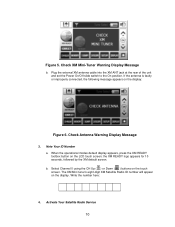
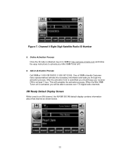
... jack at the rear of the unit and set the Power On/Off slide switch to the On position. The XM Mini tuner's eight-digit XM Satellite Radio ID number will appear on the display: Figure 6. Note Your ID Number a. b. If the antenna is faulty ...following message appears on the display. Check Antenna Warning Display Message 3. Activate Your Satellite Radio Service 10 Check XM Mini-Tuner Warning Display Message b. When the operational modes default display appears, press the XM READY toolbox button on the touch screen. Write the number here: 4. Select Channel 0 using the CH ...
... jack at the rear of the unit and set the Power On/Off slide switch to the On position. The XM Mini tuner's eight-digit XM Satellite Radio ID number will appear on the display: Figure 6. Note Your ID Number a. b. If the antenna is faulty ...following message appears on the display. Check Antenna Warning Display Message 3. Activate Your Satellite Radio Service 10 Check XM Mini-Tuner Warning Display Message b. When the operational modes default display appears, press the XM READY toolbox button on the touch screen. Write the number here: 4. Select Channel 0 using the CH ...
User Manual
Page 12
...Call XM® at least 1 hour. When the Mini XM® Tuner unit is activated, you should keep your Mini XM® Tuner unit. 6. After the activation form is obtained, log on to XM® at http://activate.xmradio.com and follow the easy instructions to activate your receiver ON for at 1-800-XM ...walk you through the activation process. XM Ready Default Display Screen While tuned to access over 170 digital radio channels. Online Activation Process Once the ID code is submitted you will be able to an XM channel, the NVXM1000 XM default display contains information about that channel...
...Call XM® at least 1 hour. When the Mini XM® Tuner unit is activated, you should keep your Mini XM® Tuner unit. 6. After the activation form is obtained, log on to XM® at http://activate.xmradio.com and follow the easy instructions to activate your receiver ON for at 1-800-XM ...walk you through the activation process. XM Ready Default Display Screen While tuned to access over 170 digital radio channels. Online Activation Process Once the ID code is submitted you will be able to an XM channel, the NVXM1000 XM default display contains information about that channel...