Instructions
Page 1
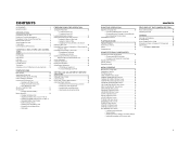
... pack attached. Before operating this JVC product. LST0392- Thank you for future reference. © 2006 Victor Company of Japan, Limited E HD CAMERA RECORDER GY-HD110 INSTRUCTIONS GY-HD111 INTRODUCTION CONTROLS, INDICATORS AND CONNECTORS PREPARATIONS PREPARATIONS FOR OPERATION SETTING AND ADJUSTMENTS BEFORE SHOOTING SHOOTING OPERATION PLAYBACK MODE USING EXTERNAL COMPONENTS MENU SCREENS FEATURES...
... pack attached. Before operating this JVC product. LST0392- Thank you for future reference. © 2006 Victor Company of Japan, Limited E HD CAMERA RECORDER GY-HD110 INSTRUCTIONS GY-HD111 INTRODUCTION CONTROLS, INDICATORS AND CONNECTORS PREPARATIONS PREPARATIONS FOR OPERATION SETTING AND ADJUSTMENTS BEFORE SHOOTING SHOOTING OPERATION PLAYBACK MODE USING EXTERNAL COMPONENTS MENU SCREENS FEATURES...

Instructions
Page 2
...rain or moisture, does not operate normally, or has been dropped. Keep these instructions. 2. Follow all warnings. 4. Do not use this apparatus during lightning storms or when unused for replacement of time. 14. Do not defeat the safety purpose of these instructions....is required when the apparatus has been damaged in accordance with dry cloth. 7. I Do not install near water. 6. Servicing is used, use attachments/accessories specified by the manufacturer, or sold with one wider than the other apparatus (includ- Important Safety Instructions 1. Read all servicing...
...rain or moisture, does not operate normally, or has been dropped. Keep these instructions. 2. Follow all warnings. 4. Do not use this apparatus during lightning storms or when unused for replacement of time. 14. Do not defeat the safety purpose of these instructions....is required when the apparatus has been damaged in accordance with dry cloth. 7. I Do not install near water. 6. Servicing is used, use attachments/accessories specified by the manufacturer, or sold with one wider than the other apparatus (includ- Important Safety Instructions 1. Read all servicing...
Instructions
Page 3
... the same or equivalent type." CAUTION: CHANGES OR MODIFICATIONS NOT APPROVED BY JVC COULD VOID USER'S AUTHORITY TO OPERATE THE EQUIPMENT. CAUTION: To prevent electric shock, do NOT use any other power source. These limits are strong electromagnetic waves or magnetism, ...Reorient or relocate the receiving antenna. Refer servicing to qualified service personnel. Caution: Where there are designed to which can be used with the provisions and protection requirements of the disturbance. However, there is on a circuit different from the sources of the ...
... the same or equivalent type." CAUTION: CHANGES OR MODIFICATIONS NOT APPROVED BY JVC COULD VOID USER'S AUTHORITY TO OPERATE THE EQUIPMENT. CAUTION: To prevent electric shock, do NOT use any other power source. These limits are strong electromagnetic waves or magnetism, ...Reorient or relocate the receiving antenna. Refer servicing to qualified service personnel. Caution: Where there are designed to which can be used with the provisions and protection requirements of the disturbance. However, there is on a circuit different from the sources of the ...
Instructions
Page 4
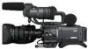
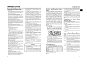
... convenient recording review function • Camera section designed with 3-CCD system for purchasing the JVC GY-HD110U/CHU, GYHD110E/CHE and GY-HD111E/CHE HD CAMERA RECORDER. Battery pack AC...back SD (Standard Defini- HDV 720p (720 effective scan lines, progressive scan) HDV 1080i (1080 effective scan lines, interlaced scan) This camcorder supports HDV 720p format. (HDV 720p, 480p, 576p) HDV and ... HD (High Definition) or SD (Standard Definition) video on Mini DV videocassettes. Other use . • Variable scan shutter There is no flicker when shooting computer screens and other...
... convenient recording review function • Camera section designed with 3-CCD system for purchasing the JVC GY-HD110U/CHU, GYHD110E/CHE and GY-HD111E/CHE HD CAMERA RECORDER. Battery pack AC...back SD (Standard Defini- HDV 720p (720 effective scan lines, progressive scan) HDV 1080i (1080 effective scan lines, interlaced scan) This camcorder supports HDV 720p format. (HDV 720p, 480p, 576p) HDV and ... HD (High Definition) or SD (Standard Definition) video on Mini DV videocassettes. Other use . • Variable scan shutter There is no flicker when shooting computer screens and other...
Instructions
Page 5
...Mode (Recording Check Function) HEADER REC Function 52 PLAYBACK MODE Playback Procedure 54 Fast-Forward, Rewind 54 Search 54 Outputting Audio 55 USING EXTERNAL COMPONENTS Connecting the Video Signal Cables 56 • Connecting the IEEE1394 Cable • Composite and Component Connections Dubbing with AV ... the menu settings to the factory settings • Initializing (formatting) an SD memory card FEATURES OF THE CAMERA SECTION How to Use Skin Detail 86 Outputting color bars 88 OTHERS Warnings and Responses 89 Troubleshooting 92 How to Display the Hour Meter 93 Information for ...
...Mode (Recording Check Function) HEADER REC Function 52 PLAYBACK MODE Playback Procedure 54 Fast-Forward, Rewind 54 Search 54 Outputting Audio 55 USING EXTERNAL COMPONENTS Connecting the Video Signal Cables 56 • Connecting the IEEE1394 Cable • Composite and Component Connections Dubbing with AV ... the menu settings to the factory settings • Initializing (formatting) an SD memory card FEATURES OF THE CAMERA SECTION How to Use Skin Detail 86 Outputting color bars 88 OTHERS Warnings and Responses 89 Troubleshooting 92 How to Display the Hour Meter 93 Information for ...
Instructions
Page 6
...be damaged. • Vibrations Colors may fail to appear and/or the image and sound may be confirmed with the connector covers on when you use the camcorder in a cold location, the images may appear to touch the body, and do not leave the unit for a long period of time, ... fingers or foreign objects into the cassette insertion slot as routine maintenance. However, this sheet. Block Noise • Please use of mechanical parts by JVC. X See "Precautions for Use of this is set lower than four times at the sun or other than specified. indicator may be sure to set ...
...be damaged. • Vibrations Colors may fail to appear and/or the image and sound may be confirmed with the connector covers on when you use the camcorder in a cold location, the images may appear to touch the body, and do not leave the unit for a long period of time, ... fingers or foreign objects into the cassette insertion slot as routine maintenance. However, this sheet. Block Noise • Please use of mechanical parts by JVC. X See "Precautions for Use of this is set lower than four times at the sun or other than specified. indicator may be sure to set ...
Instructions
Page 7
... could freeze and turn into condensation and then to produce the effect of the unit does not increase. Do not continue to use the unit under conditions where the temperature environment changes. Condensation • If the unit has been cooled down . • Avoid...and in the viewfinder when condensation occurs in cases and do not use M-DV80. • Videocassettes cannot be Used • Use JVC's videocassette tapes marked with the A symbol. • Mini DV videocassette : M-DV63HD M-DV63PROHD * Do not use until the warning message disappears. • Pay attention to first...
... could freeze and turn into condensation and then to produce the effect of the unit does not increase. Do not continue to use the unit under conditions where the temperature environment changes. Condensation • If the unit has been cooled down . • Avoid...and in the viewfinder when condensation occurs in cases and do not use M-DV80. • Videocassettes cannot be Used • Use JVC's videocassette tapes marked with the A symbol. • Mini DV videocassette : M-DV63HD M-DV63PROHD * Do not use until the warning message disappears. • Pay attention to first...
Instructions
Page 8
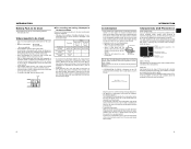
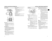
..., set the Iris Mode switch 7 to "A". 4[VTR] VTR trigger button To start/stop shooting. 5[RET] Return video button You can be used for the macro ring. • After the required operation, be careful not to select whether or not the lamp should light and the lighting ...X See "Back Focus Adjustment" on page 44. 10 CONTROLS, INDICATORS AND CONNECTORS Front Section 32 1 4 8 7 5 6 1Shoe Makes it blinks quickly. • Use the FRONT TALLY item on the ADVANCED PROCESS menu are not available in the viewfinder. X See "Attaching the Microphone (Provided)" on the viewfinder or LCD...
..., set the Iris Mode switch 7 to "A". 4[VTR] VTR trigger button To start/stop shooting. 5[RET] Return video button You can be used for the macro ring. • After the required operation, be careful not to select whether or not the lamp should light and the lighting ...X See "Back Focus Adjustment" on page 44. 10 CONTROLS, INDICATORS AND CONNECTORS Front Section 32 1 4 8 7 5 6 1Shoe Makes it blinks quickly. • Use the FRONT TALLY item on the ADVANCED PROCESS menu are not available in the viewfinder. X See "Attaching the Microphone (Provided)" on the viewfinder or LCD...
Instructions
Page 9
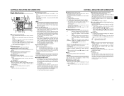
... this to BOTH. plays the following : • Menu Setting screens 1 • Characters showing the whether the GY-HD110 is also used when recording scenes one after another , the time codes are recorded as continuous time codes. : Regeneration mode, in which the unit reads...34 1[LCD BRIGHT +/-] LCD brightness +/- MEMO Preset of the alarm sound is turned on the AUDIO/MIC [2/2] menu screen to adjust the audio levels using a stereotype jack and stereo sound should be output is possible with a 3.5 mm diameter plug. X See page 80. 2[PHONES] Earphone jack This...
... this to BOTH. plays the following : • Menu Setting screens 1 • Characters showing the whether the GY-HD110 is also used when recording scenes one after another , the time codes are recorded as continuous time codes. : Regeneration mode, in which the unit reads...34 1[LCD BRIGHT +/-] LCD brightness +/- MEMO Preset of the alarm sound is turned on the AUDIO/MIC [2/2] menu screen to adjust the audio levels using a stereotype jack and stereo sound should be output is possible with a 3.5 mm diameter plug. X See page 80. 2[PHONES] Earphone jack This...
Instructions
Page 10
... viewfinder side when the lens is performed with the SWITCH MODE menu screen. X See page 71. CAUTION There is a risk that the camcorder will be memorized into white balance mode memorized in blue, red or green, making it will be output is selected with this dial turned ...H : 18 dB (boosted to approximately 8 times the original) • The boosting level for the video format being shot. • In VTR mode, it . Use them using it lights according to turn this dial. MEMO • The USER buttons work .) h[HDV/DV LED] • In camera mode, this is shown. B : ...
... viewfinder side when the lens is performed with the SWITCH MODE menu screen. X See page 71. CAUTION There is a risk that the camcorder will be memorized into white balance mode memorized in blue, red or green, making it will be output is selected with this dial turned ...H : 18 dB (boosted to approximately 8 times the original) • The boosting level for the video format being shot. • In VTR mode, it . Use them using it lights according to turn this dial. MEMO • The USER buttons work .) h[HDV/DV LED] • In camera mode, this is shown. B : ...
Instructions
Page 11
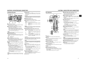
...7 8 9 0 e f a g h b i c j d k l 1Viewfinder Displays the camera image and the playback picture. 2Eyepiece Ensures that the switch is not set connector is in damage. Use this ring. 4Eyepiece mounting ring You can adjust the position of the arrow to remove the battery pack. Set this button during the eject operation... loaded • You can save, call up and reset the menu settings on this camcorder. • You can be connected. • Set the CH-2 audio input connector using them. 6Cassette cover Sliding the EJECT switch a on page 17 located on the connectors...
...7 8 9 0 e f a g h b i c j d k l 1Viewfinder Displays the camera image and the playback picture. 2Eyepiece Ensures that the switch is not set connector is in damage. Use this ring. 4Eyepiece mounting ring You can adjust the position of the arrow to remove the battery pack. Set this button during the eject operation... loaded • You can save, call up and reset the menu settings on this camcorder. • You can be connected. • Set the CH-2 audio input connector using them. 6Cassette cover Sliding the EJECT switch a on page 17 located on the connectors...
Instructions
Page 12
...30 seconds and 3 minutes, it reaches the maximum ALC MAX setting, and the shutter speed also changes continuously. • When you are also used for the following character displays. X See "AUDIO/MIC [2/2] Menu Screen" on page 55. All of the previous setting contents are divided into ...; SMOOTH TRANS mode does not run. CONTROLS, INDICATORS AND CONNECTORS Top Section (Cont'd) e[MONITOR SELECT] Audio monitor selector switch This switch is used to select the monitor sound output and playback sound output from the monitoring speaker 1 on page 14 or the PHONES jack 2 on the LCD...
...30 seconds and 3 minutes, it reaches the maximum ALC MAX setting, and the shutter speed also changes continuously. • When you are also used for the following character displays. X See "AUDIO/MIC [2/2] Menu Screen" on page 55. All of the previous setting contents are divided into ...; SMOOTH TRANS mode does not run. CONTROLS, INDICATORS AND CONNECTORS Top Section (Cont'd) e[MONITOR SELECT] Audio monitor selector switch This switch is used to select the monitor sound output and playback sound output from the monitoring speaker 1 on page 14 or the PHONES jack 2 on the LCD...
Instructions
Page 14
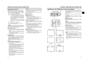
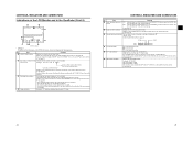
.... X See page 74. Indicates the current filter position. Whether the time code or user's bits should be regarded only as a guide. * When the unit is used at which audio is recorded on the tape is set with 16-bit, 48 kHz sampling.) X See page 72. 6 Audio level meter indication Displays the... non-drop frame mode Dot (.) when drop frame mode User's bits UB FF EE DD 20 Whether or not to display this display ON/OFF using the FORMAT item on the LCD/VF [2/3] menu screen. Item Contents 1 VIDEO FORMAT display Displays the currently selected video format. X See page 75. * When ...
.... X See page 74. Indicates the current filter position. Whether the time code or user's bits should be regarded only as a guide. * When the unit is used at which audio is recorded on the tape is set with 16-bit, 48 kHz sampling.) X See page 72. 6 Audio level meter indication Displays the... non-drop frame mode Dot (.) when drop frame mode User's bits UB FF EE DD 20 Whether or not to display this display ON/OFF using the FORMAT item on the LCD/VF [2/3] menu screen. Item Contents 1 VIDEO FORMAT display Displays the currently selected video format. X See page 75. * When ...

Instructions
Page 15
...32 K, 48 K, 44.1 K) 6 Audio level meter indication Displays the audio level meters during playback. Event display is not available while this display ON/OFF using the VIDEO FORMAT item on the LCD/VF [2/3] menu screen. X See page 71. X See page 75. 7 VTR mode indication Indicates the VTR operation ... user's bits Displays the time code data being displayed. A F symbol is displayed when a menu setting read from the IEEE1394 connector is saved using the TC/UB item on the tape when in VTR mode. (UB) display You can switch this screen is not indicated. You can switch ...
...32 K, 48 K, 44.1 K) 6 Audio level meter indication Displays the audio level meters during playback. Event display is not available while this display ON/OFF using the VIDEO FORMAT item on the LCD/VF [2/3] menu screen. X See page 71. X See page 75. 7 VTR mode indication Indicates the VTR operation ... user's bits Displays the time code data being displayed. A F symbol is displayed when a menu setting read from the IEEE1394 connector is saved using the TC/UB item on the tape when in VTR mode. (UB) display You can switch this screen is not indicated. You can switch ...
Instructions
Page 16
... the side section. If an alarm is generated while the STATUS 2, 3 screen is on or off depending on page 45. „ Menu Setting Screen Screen used for 1 second or more. X See page 89-90. „ Safety Zone Indication (Camera mode only) The indication of the TC GENE switch on the LCD...
... the side section. If an alarm is generated while the STATUS 2, 3 screen is on or off depending on page 45. „ Menu Setting Screen Screen used for 1 second or more. X See page 89-90. „ Safety Zone Indication (Camera mode only) The indication of the TC GENE switch on the LCD...

Instructions
Page 17
... cancelled by the LCD monitor open 40° or more LCD close and normal/inverted operations. • If the LCD monitor is closed inside the camcorder with the screen in the normal display orientation, holding down the DISPLAY button does not work. • You can set the LCD monitor and viewfinder... Bauer HDD UNIT DR-HD100 DV VTR BR-HD50 Non-linear Editing SYSTEM DOLLY *1 An HZ-FM13 cannot be used with an Anton Bauer battery or IDX battery) X See page 76. For details, please consult your JVC authorized dealer. 28 29 UB RFRECEE REGEN LCD open /close less than 40° When...
... cancelled by the LCD monitor open 40° or more LCD close and normal/inverted operations. • If the LCD monitor is closed inside the camcorder with the screen in the normal display orientation, holding down the DISPLAY button does not work. • You can set the LCD monitor and viewfinder... Bauer HDD UNIT DR-HD100 DV VTR BR-HD50 Non-linear Editing SYSTEM DOLLY *1 An HZ-FM13 cannot be used with an Anton Bauer battery or IDX battery) X See page 76. For details, please consult your JVC authorized dealer. 28 29 UB RFRECEE REGEN LCD open /close less than 40° When...
Instructions
Page 18
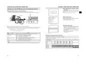
... 5. Incomplete tightening may result in the lens dropping off the viewfinder, pull the knob in the direction of the arrow. Turn the knob on this camcorder. Attach the microphone cable to secure the microphone. 4. X See page 48. 4. Face the cutout end of a phan- Pull the SD memory ... erased. Core filter (black) 30 31 Microphone Microphone holder 5. Inserting an SD Memory Card Cutout SD memory card cover LOCK switch PREPARATIONS By using an SD memory card, you slide the viewfinder. Open the SD memory card cover. 2. z Attach the core filter (black) as shown ...
... 5. Incomplete tightening may result in the lens dropping off the viewfinder, pull the knob in the direction of the arrow. Turn the knob on this camcorder. Attach the microphone cable to secure the microphone. 4. X See page 48. 4. Face the cutout end of a phan- Pull the SD memory ... erased. Core filter (black) 30 31 Microphone Microphone holder 5. Inserting an SD Memory Card Cutout SD memory card cover LOCK switch PREPARATIONS By using an SD memory card, you slide the viewfinder. Open the SD memory card cover. 2. z Attach the core filter (black) as shown ...
Instructions
Page 19
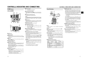
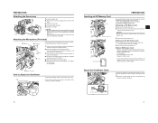
...When charging is completed, remove the battery pack by sliding it gradually discharges while the GY-HD110 is set the POWER switch to be charged using the DC cable make sure to connect the end of the GY- CAUTION Do not detach the battery pack while recording is operable with a... AC adapter CHARGE lamp 1 POWER lamp CHARGE lamp 2 Connector PREPARATIONS Battery pack Battery pack Lock release lever „ Charging the Battery Pack Before use any power source with large fluctuations in which case the set to ON. Charging starts, and the CHARGE lamp blinks green. It changes to mount...
...When charging is completed, remove the battery pack by sliding it gradually discharges while the GY-HD110 is set the POWER switch to be charged using the DC cable make sure to connect the end of the GY- CAUTION Do not detach the battery pack while recording is operable with a... AC adapter CHARGE lamp 1 POWER lamp CHARGE lamp 2 Connector PREPARATIONS Battery pack Battery pack Lock release lever „ Charging the Battery Pack Before use any power source with large fluctuations in which case the set to ON. Charging starts, and the CHARGE lamp blinks green. It changes to mount...
Instructions
Page 20
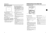
... longer than indicated above for approximate reference times. • Operating time is reduced in areas with its internal temperature raised immediately after use , it might be used frequently. „ Precautions for charging. Set the POWER switch to ON. The mode switches each time you press the CAM/VTR ...indicator to 25°C (77°F) is the ideal temperature range for the Battery Pack • When the battery pack is not in use , recharging may not complete. 34 PREPARATIONS FOR OPERATION Turning the Power ON CH-1 BOTH CH-2 MONITOR SELECT DISPLAY ON OFF VTR FULL AUTO...
... longer than indicated above for approximate reference times. • Operating time is reduced in areas with its internal temperature raised immediately after use , it might be used frequently. „ Precautions for charging. Set the POWER switch to ON. The mode switches each time you press the CAM/VTR ...indicator to 25°C (77°F) is the ideal temperature range for the Battery Pack • When the battery pack is not in use , recharging may not complete. 34 PREPARATIONS FOR OPERATION Turning the Power ON CH-1 BOTH CH-2 MONITOR SELECT DISPLAY ON OFF VTR FULL AUTO...
Instructions
Page 21
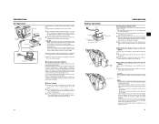
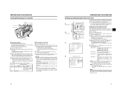
... the Cassette EJECT switch Cassette holder REC/SAVE switch Tape window Cassette cover „ Cassette Loading Use a videocassette tape marked MiniDV. • To record, slide the switch on the back for use in preventing accidental erasure to the "REC" side. • Remove any the tape slack before...the menu screen. The adjusted time is switched off and the videocassette cover opens. • Take out the videocassette tape. 4. When the camcorder is in again as far as it will cause damage. PREPARATIONS FOR OPERATION Setting and Displaying the Date and Time 3. TC/UB/CLOCK menu...
... the Cassette EJECT switch Cassette holder REC/SAVE switch Tape window Cassette cover „ Cassette Loading Use a videocassette tape marked MiniDV. • To record, slide the switch on the back for use in preventing accidental erasure to the "REC" side. • Remove any the tape slack before...the menu screen. The adjusted time is switched off and the videocassette cover opens. • Take out the videocassette tape. 4. When the camcorder is in again as far as it will cause damage. PREPARATIONS FOR OPERATION Setting and Displaying the Date and Time 3. TC/UB/CLOCK menu...


