Instructions
Page 3
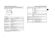
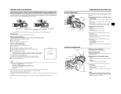
... from the sources of important operating and maintenance (servicing) instructions in a particular installation. CAUTION: CHANGES OR MODIFICATIONS NOT APPROVED BY JVC COULD VOID USER'S AUTHORITY TO OPERATE THE EQUIPMENT. Cet appareil numerique de la Class B est conforme a la norme NMB-003 ...TO RAIN OR MOISTURE. Refer servicing to be used in the following length: Camera Port DC INPUT INPUT1/2 LINE OUTPUT PHONES 1/2 VIDEO/Y, PB, PR IEEE1394 (HDV/DV) Cable Exclusive Cable Shielded Cable Shielded Cable Shielded Cable Shielded Cable Exclusive Cable Length 2 m 3 m 1.5 m 2 m 3 m 4.5 m AC ...
... from the sources of important operating and maintenance (servicing) instructions in a particular installation. CAUTION: CHANGES OR MODIFICATIONS NOT APPROVED BY JVC COULD VOID USER'S AUTHORITY TO OPERATE THE EQUIPMENT. Cet appareil numerique de la Class B est conforme a la norme NMB-003 ...TO RAIN OR MOISTURE. Refer servicing to be used in the following length: Camera Port DC INPUT INPUT1/2 LINE OUTPUT PHONES 1/2 VIDEO/Y, PB, PR IEEE1394 (HDV/DV) Cable Exclusive Cable Shielded Cable Shielded Cable Shielded Cable Shielded Cable Exclusive Cable Length 2 m 3 m 1.5 m 2 m 3 m 4.5 m AC ...
Instructions
Page 4
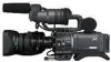
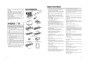
... Definition) video on the rights of copyright holders. • JVC cannot assume liabilities that both 60 Hz/50 Hz HD or HDTV signals. HDV 720p (720 effective scan lines, progressive scan) HDV 1080i (1080 effective scan lines, interlaced scan) This camcorder supports HDV 720p format. (HDV 720p, 480p, 576p) HDV and are trademarks of Sony Corporation and Victor Company of...
... Definition) video on the rights of copyright holders. • JVC cannot assume liabilities that both 60 Hz/50 Hz HD or HDTV signals. HDV 720p (720 effective scan lines, progressive scan) HDV 1080i (1080 effective scan lines, interlaced scan) This camcorder supports HDV 720p format. (HDV 720p, 480p, 576p) HDV and are trademarks of Sony Corporation and Victor Company of...
Instructions
Page 5
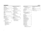
... 55 USING EXTERNAL COMPONENTS Connecting the Video Signal Cables 56 • Connecting the IEEE1394 Cable • Composite and Component Connections Dubbing with AV Devices 57 HDV/DV Dubbing 58 Backup Recording 60 MENU SCREENS Menu Screen Configuration 61 Setting Menu Screens 62 TOP MENU Screen 63 VIDEO FORMAT Menu Screen 64...
... 55 USING EXTERNAL COMPONENTS Connecting the Video Signal Cables 56 • Connecting the IEEE1394 Cable • Composite and Component Connections Dubbing with AV Devices 57 HDV/DV Dubbing 58 Backup Recording 60 MENU SCREENS Menu Screen Configuration 61 Setting Menu Screens 62 TOP MENU Screen 63 VIDEO FORMAT Menu Screen 64...
Instructions
Page 9
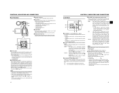
...mode : Off • Select the Camera mode to record the camera image. • Select the VTR mode to playback VTR or to input the HDV/DV signal from falling off the tripod. It is possible with a 3.5 mm diameter plug. Always make sure that the camera is also used to monitor... anew (preset). The earphone can also be performed. buttons simultaneously returns the setting to prevent the camera from the IEEE1394 connector 4 on page 16. (HDV/DV signal input is also used for audio monitoring. It is securely mounted. 6 5 1Back tally lamp This lamp lights up when the GY-HD110 enters...
...mode : Off • Select the Camera mode to record the camera image. • Select the VTR mode to playback VTR or to input the HDV/DV signal from falling off the tripod. It is possible with a 3.5 mm diameter plug. Always make sure that the camera is also used to monitor... anew (preset). The earphone can also be performed. buttons simultaneously returns the setting to prevent the camera from the IEEE1394 connector 4 on page 16. (HDV/DV signal input is also used for audio monitoring. It is securely mounted. 6 5 1Back tally lamp This lamp lights up when the GY-HD110 enters...
Instructions
Page 10
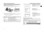
...pressed. Use them using the USER1 - 3 items in the SWITCH MODE menu screen. X See page 71. MEMO • The USER buttons work .) h[HDV/DV LED] • In camera mode, this lights according to the setting for automatic adjustment to a proper white balance. • When the FULL AUTO...depending on the switch position as menu operation buttons. dStand When attaching the lens, slide the stand forward. CAUTION There is a risk that the camcorder will be EE monitored. f[REC] REC trigger button (start /stop recording using it will be output is selected with the MONITOR SELECT switch ...
...pressed. Use them using the USER1 - 3 items in the SWITCH MODE menu screen. X See page 71. MEMO • The USER buttons work .) h[HDV/DV LED] • In camera mode, this lights according to the setting for automatic adjustment to a proper white balance. • When the FULL AUTO...depending on the switch position as menu operation buttons. dStand When attaching the lens, slide the stand forward. CAUTION There is a risk that the camcorder will be EE monitored. f[REC] REC trigger button (start /stop recording using it will be output is selected with the MONITOR SELECT switch ...
Instructions
Page 11
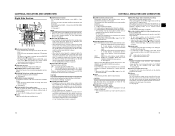
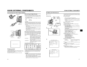
... input for component or composite video signal output. X See "HDV/DV Dubbing" on the right panel and the lens VTR trigger button are connectors for 7.2 V DC accepts the supplied AC adapter. Use this camcorder. • You can select the output signal using them. 6Cassette...8226; Set the CH-2 audio input connector using this button. (This works together with the cover open this position when a microphone requir- HDV : For HDV format DV : DV format 4[IEEE1394] IEEE1394 connector (6-pin) Using an IEEE1394 cable (optional), a digital video component with AV Devices" on...
... input for component or composite video signal output. X See "HDV/DV Dubbing" on the right panel and the lens VTR trigger button are connectors for 7.2 V DC accepts the supplied AC adapter. Use this camcorder. • You can select the output signal using them. 6Cassette...8226; Set the CH-2 audio input connector using this button. (This works together with the cover open this position when a microphone requir- HDV : For HDV format DV : DV format 4[IEEE1394] IEEE1394 connector (6-pin) Using an IEEE1394 cable (optional), a digital video component with AV Devices" on...
Instructions
Page 12
... for the following character displays. Do not leave a switch stopped in the VTR mode. Noise will occur. To perform VTR playback or to input the HDV/DV signal from the IEEE1394 connector 4 on page 16, press the CAM/VTR button 5 on page13 to turn on the AUDIO/MIC [2/2] menu screen is... maximum ALC MAX setting, and the shutter speed also changes continuously. • When you are output mixed. It flashes when the mode is being changed. (HDV/DV signal input is possible with the GY-HD110U, GYHD111E.) h[FULL AUTO] Full auto shooting (FAS) switch This is the ON/OFF switch for VTR...
... for the following character displays. Do not leave a switch stopped in the VTR mode. Noise will occur. To perform VTR playback or to input the HDV/DV signal from the IEEE1394 connector 4 on page 16, press the CAM/VTR button 5 on page13 to turn on the AUDIO/MIC [2/2] menu screen is... maximum ALC MAX setting, and the shutter speed also changes continuously. • When you are output mixed. It flashes when the mode is being changed. (HDV/DV signal input is possible with the GY-HD110U, GYHD111E.) h[FULL AUTO] Full auto shooting (FAS) switch This is the ON/OFF switch for VTR...
Instructions
Page 13
... on page 83-85. Setting Status Contents of date and time Indicates the date and time. A REC command was sent from the IEEE1394 TRIGGER TO HDV, TRIGGER TO DV connector Other Displays X See "FILE MANAGE Menu Screen" on the video format. X See page 71. *3 Displayed when the [WHT.BAL] white balance...
... on page 83-85. Setting Status Contents of date and time Indicates the date and time. A REC command was sent from the IEEE1394 TRIGGER TO HDV, TRIGGER TO DV connector Other Displays X See "FILE MANAGE Menu Screen" on the video format. X See page 71. *3 Displayed when the [WHT.BAL] white balance...

Instructions
Page 15
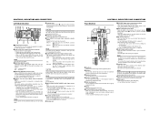
... date and time should be displayed and the display style are set , the following indication appears. 9 Voltage indication (Example) 7.0V : Indicates remaining battery level in HDV format, the data of the remaining tape time appears. 4 Event display Displays messages related to less than 3 minutes. X See "Displaying the Time and Date on...
... date and time should be displayed and the display style are set , the following indication appears. 9 Voltage indication (Example) 7.0V : Indicates remaining battery level in HDV format, the data of the remaining tape time appears. 4 Event display Displays messages related to less than 3 minutes. X See "Displaying the Time and Date on...
Instructions
Page 16
... recorded in the VTR, a warning mes- SAFETY ZONE CENTER MARK REC ASPECT DV-60I DV-24P 4:3 DV-24PA DV-50I DV-25P 16:9 HDV-SD60P HDV-SD50P HDV-HD30P HDV-HD25P HDV-HD24P [16:9] OFF - 4:3 OFF ON 14:9 OFF ON 16:9 OFF ON 16:9+4:3 OFF ON Cannot be selected 26 27 DUPL : There is set...
... recorded in the VTR, a warning mes- SAFETY ZONE CENTER MARK REC ASPECT DV-60I DV-24P 4:3 DV-24PA DV-50I DV-25P 16:9 HDV-SD60P HDV-SD50P HDV-HD30P HDV-HD25P HDV-HD24P [16:9] OFF - 4:3 OFF ON 14:9 OFF ON 16:9 OFF ON 16:9+4:3 OFF ON Cannot be selected 26 27 DUPL : There is set...
Instructions
Page 20
... in the Camera mode. "STBY" is displayed in the VTR operation mode indication area of the battery pack, charging conditions and the operating environment, etc. HDV/DV input is being switched : Flashing In VTR mode : Lit In Camera mode : Off Camera mode The GY-HD110 enters the Camera mode. If the...
... in the Camera mode. "STBY" is displayed in the VTR operation mode indication area of the battery pack, charging conditions and the operating environment, etc. HDV/DV input is being switched : Flashing In VTR mode : Lit In Camera mode : Off Camera mode The GY-HD110 enters the Camera mode. If the...
Instructions
Page 22
...downward, the value becomes smaller. 3Repeat the procedure described in 1 and 2 above to display them are shown on the TIME/DATE menu screen. 1. When an HDV/DV sig- : The date and time of the blinking digit changes. UB : User's bit data is displayed. „ Time code input entered the IEEE1394... code and user's bit from the are displayed. When the SHUTTER dial is input from the IEEE1394 connector, set on the LCD monitor or in HDV format. (GY- The digits indicating seconds cannot be output through the unit's con- DATE : Date only is selected with the TC DISPLAY switch ...
...downward, the value becomes smaller. 3Repeat the procedure described in 1 and 2 above to display them are shown on the TIME/DATE menu screen. 1. When an HDV/DV sig- : The date and time of the blinking digit changes. UB : User's bit data is displayed. „ Time code input entered the IEEE1394... code and user's bit from the are displayed. When the SHUTTER dial is input from the IEEE1394 connector, set on the LCD monitor or in HDV format. (GY- The digits indicating seconds cannot be output through the unit's con- DATE : Date only is selected with the TC DISPLAY switch ...
Instructions
Page 24
... screen image is not synchronized, it will be turned 180° in upward direction and 90° in downward direction. Press the USER1 button to HDV format, frame digit may deviate. „ If power is turned off, slave lock is disabled. switch on the LCD/VF [1/3] menu screen. Adjustments are displayed... in magnified size, images and characters are made on the slave unit is not set to FREE • The slave unit is GY-HD110E • HDV format „ If slave lock is performed in DV format and is then switched to begin slave lock. (To skip slave lock, press the USER3...
... screen image is not synchronized, it will be turned 180° in upward direction and 90° in downward direction. Press the USER1 button to HDV format, frame digit may deviate. „ If power is turned off, slave lock is disabled. switch on the LCD/VF [1/3] menu screen. Adjustments are displayed... in magnified size, images and characters are made on the slave unit is not set to FREE • The slave unit is GY-HD110E • HDV format „ If slave lock is performed in DV format and is then switched to begin slave lock. (To skip slave lock, press the USER3...

Instructions
Page 26
... during live output or shooting. 46 SETTING AND ADJUSTMENTS BEFORE SHOOTING Camera Settings VTR indicator 4. 3. 1. X See page 68. Set the shutter speed to HDV format, the ASPECT item is fixed at least 1 second. • The TOP MENU screen is displayed on the VIDEO FORMAT menu to OFF with normal... CHANGE" is displayed on the screen and after a few seconds the system is displayed. • If the above applies, you set to HDV-HD30P, HDV-HD25P or HDV-HD24P, the video can be selected with the ASPECT item on the 16:9 television you are using the 16:9 screen, set ASPECT to the...
... during live output or shooting. 46 SETTING AND ADJUSTMENTS BEFORE SHOOTING Camera Settings VTR indicator 4. 3. 1. X See page 68. Set the shutter speed to HDV format, the ASPECT item is fixed at least 1 second. • The TOP MENU screen is displayed on the VIDEO FORMAT menu to OFF with normal... CHANGE" is displayed on the screen and after a few seconds the system is displayed. • If the above applies, you set to HDV-HD30P, HDV-HD25P or HDV-HD24P, the video can be selected with the ASPECT item on the 16:9 television you are using the 16:9 screen, set ASPECT to the...

Instructions
Page 28
... seconds of focus is shown on the LCD monitor, in the viewfinder or on the tape where the RET button was recorded in HDV format can be rewound and played back. • Pressing the REC/VTR trigger button during recording. "HEAD CLEANING REQUIRED!" SHOOTING OPERATION...back. SHOOTING OPERATION „ Checking Recorded Contents in the viewfinder screen. (STATUS 1 screen) „ To start recording. After playback, the camcorder returns to the tape protect mode. is shown on the LCD monitor and in RecordStandby Mode (Recording Check Function) This function is available only when...
... seconds of focus is shown on the LCD monitor, in the viewfinder or on the tape where the RET button was recorded in HDV format can be rewound and played back. • Pressing the REC/VTR trigger button during recording. "HEAD CLEANING REQUIRED!" SHOOTING OPERATION...back. SHOOTING OPERATION „ Checking Recorded Contents in the viewfinder screen. (STATUS 1 screen) „ To start recording. After playback, the camcorder returns to the tape protect mode. is shown on the LCD monitor and in RecordStandby Mode (Recording Check Function) This function is available only when...

Instructions
Page 30
..., the tape speed decelerates to the nor- Playback takes place while fast forwarding. Display the AUDIO menu screen. Table 1 MONITOR SELECT CH-1 BOTH CH-2 * In HDV format, you to protect the tape. • The time required for a while, the unit automatically switches to the tape protect mode. PB AUDIO CH [DV...
..., the tape speed decelerates to the nor- Playback takes place while fast forwarding. Display the AUDIO menu screen. Table 1 MONITOR SELECT CH-1 BOTH CH-2 * In HDV format, you to protect the tape. • The time required for a while, the unit automatically switches to the tape protect mode. PB AUDIO CH [DV...
Instructions
Page 31
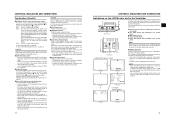
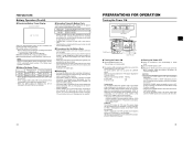
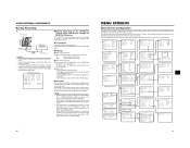
...the figure on the left. • Attach the clamp filter as close to the camcorder as possible, as shown in the figure. 2. X See page 65. Composite cable or Component cable PB VIDEO/Y IEEE 1394 HDV DV LINE OUTPUT connector 1. VIDEO FORMAT menu screen 5. AUDIO menu screen USING EXTERNAL .... • Set the IEEE1394 switch on this camcorder (VIDEO/Y, PB, PR) are different. Connect the cables. Set the camcorder to the video signal output terminal when connecting or disconnecting the cable. Set the video output. X See page 64. • HDV PB OUTPUT item: Set the video format to ...
...the figure on the left. • Attach the clamp filter as close to the camcorder as possible, as shown in the figure. 2. X See page 65. Composite cable or Component cable PB VIDEO/Y IEEE 1394 HDV DV LINE OUTPUT connector 1. VIDEO FORMAT menu screen 5. AUDIO menu screen USING EXTERNAL .... • Set the IEEE1394 switch on this camcorder (VIDEO/Y, PB, PR) are different. Connect the cables. Set the camcorder to the video signal output terminal when connecting or disconnecting the cable. Set the video output. X See page 64. • HDV PB OUTPUT item: Set the video format to ...

Instructions
Page 32
... the playback unit. tion. 9. MEMO • Switch the IEEE1394 switch when the camcorder is finished, stop recording on the recording device, press the STOP button on the camcorder, and stop playback on this camcorder to either HDV or DV. • Start recording after making sure that both devices to start playback... the data sent from the playback device in the audio. MEMO In HDV format, the UB set in the camcorder is completed. Press the REC/VTR trigger button on the GY-HD110 to match the HDV/DV signal frame rate input from the playback unit appears on the VIDEO...
... the playback unit. tion. 9. MEMO • Switch the IEEE1394 switch when the camcorder is finished, stop recording on the recording device, press the STOP button on the camcorder, and stop playback on this camcorder to either HDV or DV. • Start recording after making sure that both devices to start playback... the data sent from the playback device in the audio. MEMO In HDV format, the UB set in the camcorder is completed. Press the REC/VTR trigger button on the GY-HD110 to match the HDV/DV signal frame rate input from the playback unit appears on the VIDEO...
Instructions
Page 33
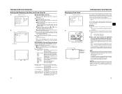
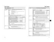
...INPUT LINE OUTPUT IEEE1394 Master unit GY-HD110 Backup unit Signal flow IEEE1394 cable CAUTION • Set the IEEE1394 switch on both devices to either HDV or DV. • Start recording after making sure that is equipped with a feature to record time codes input from the IEEE1394 connector (... used to OFF. • If the backup device is equipped with a IEEE1394 cable. „ Settings „ Master unit (GY-HD110) 1. Place in HDV format 2. Set the 1394 REC TRIGGER item on this unit, interrupting the backup recording image. TOP MENU screen (CAM) TOP MENU screen (VTR) 60 61...
...INPUT LINE OUTPUT IEEE1394 Master unit GY-HD110 Backup unit Signal flow IEEE1394 cable CAUTION • Set the IEEE1394 switch on both devices to either HDV or DV. • Start recording after making sure that is equipped with a feature to record time codes input from the IEEE1394 connector (... used to OFF. • If the backup device is equipped with a IEEE1394 cable. „ Settings „ Master unit (GY-HD110) 1. Place in HDV format 2. Set the 1394 REC TRIGGER item on this unit, interrupting the backup recording image. TOP MENU screen (CAM) TOP MENU screen (VTR) 60 61...
Instructions
Page 35
.... Setting DV-60I HDV-SD60P HDV-HD30P HDV-SD50P HDV-HD25P DV-50I DV-25P DV-24P DV-24PA HDV-HD24P Description DV format Shoots using a 720/25p signal. The resolution in the vertical direction drops compared to this item when the camcorder is in VTR mode or is ejecting a tape. Setting NATIVE 720P 1080I 480P NTSC...
.... Setting DV-60I HDV-SD60P HDV-HD30P HDV-SD50P HDV-HD25P DV-50I DV-25P DV-24P DV-24PA HDV-HD24P Description DV format Shoots using a 720/25p signal. The resolution in the vertical direction drops compared to this item when the camcorder is in VTR mode or is ejecting a tape. Setting NATIVE 720P 1080I 480P NTSC...
