
User Manual
Page 1
M-577004 Revision B1 03/2014 Copyright © 2014 JET This .pdf document is bookmarked Operating Instructions and Parts Manual Belt (2x42") and Disc (8") Sander Model J-41002 JET 427 New Sanford Road LaVergne, Tennessee 37086 Ph.: 800-274-6848 www.jettools.com Part No.
M-577004 Revision B1 03/2014 Copyright © 2014 JET This .pdf document is bookmarked Operating Instructions and Parts Manual Belt (2x42") and Disc (8") Sander Model J-41002 JET 427 New Sanford Road LaVergne, Tennessee 37086 Ph.: 800-274-6848 www.jettools.com Part No.
User Manual
Page 2
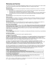
... OR EXCLUSION MAY NOT APPLY TO YOU. Light-Duty Air Tools 1 Year - Machine Accessories; Manual Hoist Accessories; Hand Tools NOTE: JET is Covered This warranty covers any reason whatsoever. Warranty Limitations Woodworking products with a Five Year Warranty that you specific legal rights, subject to -date product information, check with Warranty Period 90 Days - Electric Hoists, Electric Hoist Accessories; JET has Authorized Service Centers located throughout the United States. For...
... OR EXCLUSION MAY NOT APPLY TO YOU. Light-Duty Air Tools 1 Year - Machine Accessories; Manual Hoist Accessories; Hand Tools NOTE: JET is Covered This warranty covers any reason whatsoever. Warranty Limitations Woodworking products with a Five Year Warranty that you specific legal rights, subject to -date product information, check with Warranty Period 90 Days - Electric Hoists, Electric Hoist Accessories; JET has Authorized Service Centers located throughout the United States. For...

User Manual
Page 3
...Installing Dust Chute ...9 Installing Disc Table ...10 Installing Miter Gauge ...10 Installing Tension Handle ...10 Grounding Instructions...11 115 Volt Operation ...11 Adjustments ...12 Tilting the Belt Table ...12 Tilting the Disc Table...12 Use of the Miter Gauge ...13 Belt Platen ...13 Abrasive Belt Replacement ...14 Tracking the Abrasive Belt...14 Abrasive Disc Replacement ...15 Aluminum Disc Removal ...15 Operation ...16 Starting and Stopping the Sander...16 Belt and Disc Movement ...16 Typical Operations ...16 Extension Cords...11 Maintenance...18 Replacement Parts ...18 Troubleshooting...
...Installing Dust Chute ...9 Installing Disc Table ...10 Installing Miter Gauge ...10 Installing Tension Handle ...10 Grounding Instructions...11 115 Volt Operation ...11 Adjustments ...12 Tilting the Belt Table ...12 Tilting the Disc Table...12 Use of the Miter Gauge ...13 Belt Platen ...13 Abrasive Belt Replacement ...14 Tracking the Abrasive Belt...14 Abrasive Disc Replacement ...15 Aluminum Disc Removal ...15 Operation ...16 Starting and Stopping the Sander...16 Belt and Disc Movement ...16 Typical Operations ...16 Extension Cords...11 Maintenance...18 Replacement Parts ...18 Troubleshooting...
User Manual
Page 4
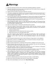
... a habit of operation. 9. Provide for maintenance purposes, use by power sanding, sawing, grinding, drilling and other part that may affect its intended function. Read and understand the entire owner's manual before connecting the machine to see that it on the machine and in the OFF position before attempting assembly or operation. 2. Always wear approved safety glasses/face shields while using this sander for the machine...
... a habit of operation. 9. Provide for maintenance purposes, use by power sanding, sawing, grinding, drilling and other part that may affect its intended function. Read and understand the entire owner's manual before connecting the machine to see that it on the machine and in the OFF position before attempting assembly or operation. 2. Always wear approved safety glasses/face shields while using this sander for the machine...
User Manual
Page 5
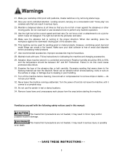
... use your dust collector is running unattended. Make sure your hands. 32. Make sure the abrasive belt is free of the abrasive disc or belt carefully. When disc sanding, place the workpiece against the abrasives or other moving parts. Turn the power off the machine before starting the machine. Do not overreach or use the sander in serious injury. 23. do this manual: This...
... use your dust collector is running unattended. Make sure your hands. 32. Make sure the abrasive belt is free of the abrasive disc or belt carefully. When disc sanding, place the workpiece against the abrasives or other moving parts. Turn the power off the machine before starting the machine. Do not overreach or use the sander in serious injury. 23. do this manual: This...
User Manual
Page 6
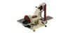
... your local supplier or JET. Specifications Model Number...J-41002 Stock Number...577004 Belt Size (in.)(LxW)...42 x 2 Belt Speed (SFPM)...3100 Disc Size (in.) ...8 diameter Disc Speed (RPM)...3450 Motor...3/4HP, 1Ph, 115V, 6.2A Belt Table Size (in.)(LxW)...10 x 6 Disc Table Size (in.)(LxW) ...10-3/4 x 7-1/2 Disc Table Tilt (deg.)...0 to change specifications at our web site: www.jettools.com. This manual contains instructions on installation, safety precautions, general operating procedures, maintenance instructions and parts breakdown. If there are any...
... your local supplier or JET. Specifications Model Number...J-41002 Stock Number...577004 Belt Size (in.)(LxW)...42 x 2 Belt Speed (SFPM)...3100 Disc Size (in.) ...8 diameter Disc Speed (RPM)...3450 Motor...3/4HP, 1Ph, 115V, 6.2A Belt Table Size (in.)(LxW)...10 x 6 Disc Table Size (in.)(LxW) ...10-3/4 x 7-1/2 Disc Table Tilt (deg.)...0 to change specifications at our web site: www.jettools.com. This manual contains instructions on installation, safety precautions, general operating procedures, maintenance instructions and parts breakdown. If there are any...
User Manual
Page 8
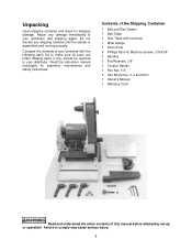
... be reported to make sure all parts are intact. Contents of the Shipping Container 1 Belt and Disc Sander 1 Belt Table 1 Disc Table with the following parts list to your distributor. Compare the contents of this manual before attempting set-up or operation! Read the instruction manual thoroughly for shipping damage. Machine Screws, 3/16x3/8" 3 Handles 3 Flat Washers, 3/8" 1 Tension Handle 1 Hex Nut, 1/4" 3 Hex Wrenches, 3, 4 and 6mm 1 Owner's Manual 1 Warranty Card Read and understand the...
... be reported to make sure all parts are intact. Contents of the Shipping Container 1 Belt and Disc Sander 1 Belt Table 1 Disc Table with the following parts list to your distributor. Compare the contents of this manual before attempting set-up or operation! Read the instruction manual thoroughly for shipping damage. Machine Screws, 3/16x3/8" 3 Handles 3 Flat Washers, 3/8" 1 Tension Handle 1 Hex Nut, 1/4" 3 Hex Wrenches, 3, 4 and 6mm 1 Owner's Manual 1 Warranty Card Read and understand the...
User Manual
Page 9
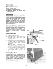
... pin. Rotate the handle back to a supporting surface. angle Sander must be unplugged from any loose parts. See Figure 1. 2. Place a flat washer onto a handle, and insert the handle through the table bracket and into the hole. The dust chute for this purpose). Leave enough space around the sander for long workpieces and for the belt is spring loaded; Screw the handle all the way into the hole. Installing Belt Table 1. screw the handle...
... pin. Rotate the handle back to a supporting surface. angle Sander must be unplugged from any loose parts. See Figure 1. 2. Place a flat washer onto a handle, and insert the handle through the table bracket and into the hole. The dust chute for this purpose). Leave enough space around the sander for long workpieces and for the belt is spring loaded; Screw the handle all the way into the hole. Installing Belt Table 1. screw the handle...

User Manual
Page 10
... guard. 2. Position the disc table at an angle, as shown in the slot to achieve this , loosen the two socket head cap screws on the hub, then tighten the hex nut against the abrasive disc. See Figure 4. 3. When finished, tighten the two socket head cap screws securely. The miter gauge can be a maximum of the workpiece against the hub. Installing Disc Table 1. Figure 3 Installing Miter Gauge Insert the miter gauge...
... guard. 2. Position the disc table at an angle, as shown in the slot to achieve this , loosen the two socket head cap screws on the hub, then tighten the hex nut against the abrasive disc. See Figure 4. 3. When finished, tighten the two socket head cap screws securely. The miter gauge can be a maximum of the workpiece against the hub. Installing Disc Table 1. Figure 3 Installing Miter Gauge Insert the miter gauge...
User Manual
Page 11
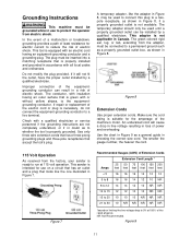
... the operator from the factory, your sander is necessary, do not connect the equipment-grounding conductor to reduce the risk of power and overheating. This tool is the equipmentgrounding conductor. The conductor, with an electric cord having an outer surface that accept the tool's plug. Use only three wire extension cords that have the proper outlet installed by a qualified electrician. This adapter...
... the operator from the factory, your sander is necessary, do not connect the equipment-grounding conductor to reduce the risk of power and overheating. This tool is the equipmentgrounding conductor. The conductor, with an electric cord having an outer surface that accept the tool's plug. Use only three wire extension cords that have the proper outlet installed by a qualified electrician. This adapter...

User Manual
Page 12
... abrasive disc, the table edge should be positioned a maximum of 1/16" from the abrasive belt. Make any adjustments to the table angle. Make any necessary adjustments to the table angle as needed. Push against the platen. 3. Figure 11 shows a square being used to confirm the zero, or horizontal position of the disc table. 3. Re-tighten the screw. 4. Tighten the handle securely. It is square with a machinist's protractor or...
... abrasive disc, the table edge should be positioned a maximum of 1/16" from the abrasive belt. Make any adjustments to the table angle. Make any necessary adjustments to the table angle as needed. Push against the platen. 3. Figure 11 shows a square being used to confirm the zero, or horizontal position of the disc table. 3. Re-tighten the screw. 4. Tighten the handle securely. It is square with a machinist's protractor or...
User Manual
Page 13
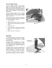
... 13 Tighten the knob. 4. Belt Platen The belt platen (Figure 13) is possible to perform operations where support of the abrasive belt. The platen should be removed for bevel sanding. The platen is almost touching the back of the belt is flush with the square, and the square is required. The platen can sand a single angle. To remove the platen, remove the socket head cap screw and washer. When using the miter gauge...
... 13 Tighten the knob. 4. Belt Platen The belt platen (Figure 13) is possible to perform operations where support of the abrasive belt. The platen should be removed for bevel sanding. The platen is almost touching the back of the belt is flush with the square, and the square is required. The platen can sand a single angle. To remove the platen, remove the socket head cap screw and washer. When using the miter gauge...

User Manual
Page 14
... Belt Replacement 1. Unplug the Sander from power source. 2. Unscrew and remove the two knobs on top of the wheel. Rotate the tension handle (Figure 6) to double check the tracking. 9. Install the new belt around the wheels. 5. Refer to the manner in small increments until the belt is positioned on /off switch quickly to secure the setting. 14 Start the sander and check the belt tracking before sanding operations (See...
... Belt Replacement 1. Unplug the Sander from power source. 2. Unscrew and remove the two knobs on top of the wheel. Rotate the tension handle (Figure 6) to double check the tracking. 9. Install the new belt around the wheels. 5. Refer to the manner in small increments until the belt is positioned on /off switch quickly to secure the setting. 14 Start the sander and check the belt tracking before sanding operations (See...
User Manual
Page 15
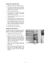
... be easily removed if needed; Rotate the disc until the set screw is properly seated in order to loosen the socket head cap screws (see Figure 4) on the motor shaft. Tighten the set screw with a 3mm hex wrench, and pull the aluminum disc off the motor shaft. 5. Reconnect sander to facilitate cleaning the aluminum disc when replacing abrasive discs. 1. To remove the disc table, remove the handles then...
... be easily removed if needed; Rotate the disc until the set screw is properly seated in order to loosen the socket head cap screws (see Figure 4) on the motor shaft. Tighten the set screw with a 3mm hex wrench, and pull the aluminum disc off the motor shaft. 5. Reconnect sander to facilitate cleaning the aluminum disc when replacing abrasive discs. 1. To remove the disc table, remove the handles then...
User Manual
Page 16
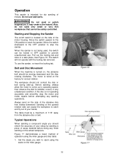
... sand on the miter gauge. 16 Figure 16 Figure 17 Set the angle you should check the accuracy of metals. Pull out the locking tab and store in OFF position to catch and fly out of your setup by sanding a piece of 1/16" away from the abrasive disc or belt. Typical Operations When sanding a compound angle you wish to start -up to stop the motor and make repairs...
... sand on the miter gauge. 16 Figure 16 Figure 17 Set the angle you should check the accuracy of metals. Pull out the locking tab and store in OFF position to catch and fly out of your setup by sanding a piece of 1/16" away from the abrasive disc or belt. Typical Operations When sanding a compound angle you wish to start -up to stop the motor and make repairs...

User Manual
Page 17
... belt table with the table tilted. • Sanding aluminum on the disc unit with your JET Sander. • Sharpening a wood chisel on the belt unit with the sanding belt. 2. Place the workpiece against the miter reference surface and slide it along the miter reference surface and into the sanding disc. The following are sanding. 3. See Figure 19. • Sanding outside curves on the sanding belt using the miter gauge as a guide...
... belt table with the table tilted. • Sanding aluminum on the disc unit with your JET Sander. • Sharpening a wood chisel on the belt unit with the sanding belt. 2. Place the workpiece against the miter reference surface and slide it along the miter reference surface and into the sanding disc. The following are sanding. 3. See Figure 19. • Sanding outside curves on the sanding belt using the miter gauge as a guide...

User Manual
Page 18
Inspect the power cord; Inspect the abrasive belt and disc. They require no further lubrication. If rust appears on the tables, use a commercial rust remover available from most hardware stores.) A light coat of paste wax on the tables will allow us to comply may cause serious injury. If either is worn, replace it from the electrical supply by pulling out the...
Inspect the power cord; Inspect the abrasive belt and disc. They require no further lubrication. If rust appears on the tables, use a commercial rust remover available from most hardware stores.) A light coat of paste wax on the tables will allow us to comply may cause serious injury. If either is worn, replace it from the electrical supply by pulling out the...

User Manual
Page 19
... proper voltage and correct if necessary. Replace abrasive belt. Replace spring. Full width of the abrasive required for recommendations on abrasive belt (and platen). Troubleshooting Trouble Probable Cause Remedy Not connected to power source. Check power source for an irregular seam or shape. Abrasive belt slips or stalls when pressure is worn. Too much pressure being used. Replace fuse/ reset circuit breaker. Abrasive disc separates...
... proper voltage and correct if necessary. Replace abrasive belt. Replace spring. Full width of the abrasive required for recommendations on abrasive belt (and platen). Troubleshooting Trouble Probable Cause Remedy Not connected to power source. Check power source for an irregular seam or shape. Abrasive belt slips or stalls when pressure is worn. Too much pressure being used. Replace fuse/ reset circuit breaker. Abrasive disc separates...

User Manual
Page 21
... 1 49 J-41002-49 Disc Guard 1 50 TS-1540061 Hex Nut M8 4 51 41002-51 Aluminum Disc 8 1 52 6291479 Key 5x5x30mm 1 53 5640211 Abrasive Disc, 100 grit 8 1 54 41002-54 Dust Chute 1 55 J-41002-55 Left Trunnion 1 56 TS-1523011 Socket Set Screw M6x6 1 21 Parts List Index No. Description Size Qty 1 J-41002-01 Base...1 2 TS-0680042 Flat Washer 3/8 2 3 TS-1551031 Lock Washer M5 4 4 TS-1515041 Socket Head Cap Screw M8x30...
... 1 49 J-41002-49 Disc Guard 1 50 TS-1540061 Hex Nut M8 4 51 41002-51 Aluminum Disc 8 1 52 6291479 Key 5x5x30mm 1 53 5640211 Abrasive Disc, 100 grit 8 1 54 41002-54 Dust Chute 1 55 J-41002-55 Left Trunnion 1 56 TS-1523011 Socket Set Screw M6x6 1 21 Parts List Index No. Description Size Qty 1 J-41002-01 Base...1 2 TS-0680042 Flat Washer 3/8 2 3 TS-1551031 Lock Washer M5 4 4 TS-1515041 Socket Head Cap Screw M8x30...
User Manual
Page 22
... Off 2 72 41002-72 Drive Wheel 1 73 TS-1523031 Socket Set Screw M6x10 1 74 41002-74 Belt Cover 1 75 41002-75 Knob ...2 76 41002-76 Tracking Wheel Cam Shaft 1 77 5513018 Retaining Ring S-17 1 78 41002-78 Tension Spring 1 79 41002-79 Spring Cap 1 80 41002-80 Handle with Knob 1 81 41002-81 Tracking Bracket 1 82 TS-1540041 Hex Nut M6 1 83 TS-1503051 Socket Head Cap Screw M6x20 1 84 41002-84 Spring Plate 2 85...
... Off 2 72 41002-72 Drive Wheel 1 73 TS-1523031 Socket Set Screw M6x10 1 74 41002-74 Belt Cover 1 75 41002-75 Knob ...2 76 41002-76 Tracking Wheel Cam Shaft 1 77 5513018 Retaining Ring S-17 1 78 41002-78 Tension Spring 1 79 41002-79 Spring Cap 1 80 41002-80 Handle with Knob 1 81 41002-81 Tracking Bracket 1 82 TS-1540041 Hex Nut M6 1 83 TS-1503051 Socket Head Cap Screw M6x20 1 84 41002-84 Spring Plate 2 85...


