Owners Manual
Page 7
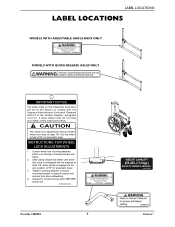
Loosen wheel lock mounting fastener, which runs through mounting bracket and frame. 2. Inspect for pneumatic tires). 3. Tighten mounting fastener to comply with the Veterans Administration functional Standard 8320.01 of the Federal Register, paragraph 3.2.4.5.3. ... rear wheel until wheel lock shoe is engaged to the lock position (3/16" for correct locking action BEFORE actual use. 00078X021-0394 Part No 1088909 7 Patriot™ LABEL LOCATIONS LABEL LOCATIONS MODELS WITH ADJUSTABLE ANGLE BACK ONLY MODELS WITH QUICK-RELEASE AXLES ONLY IMPORTANT NOTICE The wheel locks on ...
Loosen wheel lock mounting fastener, which runs through mounting bracket and frame. 2. Inspect for pneumatic tires). 3. Tighten mounting fastener to comply with the Veterans Administration functional Standard 8320.01 of the Federal Register, paragraph 3.2.4.5.3. ... rear wheel until wheel lock shoe is engaged to the lock position (3/16" for correct locking action BEFORE actual use. 00078X021-0394 Part No 1088909 7 Patriot™ LABEL LOCATIONS LABEL LOCATIONS MODELS WITH ADJUSTABLE ANGLE BACK ONLY MODELS WITH QUICK-RELEASE AXLES ONLY IMPORTANT NOTICE The wheel locks on ...
Owners Manual
Page 8
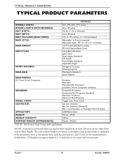
... in 1-inch increments Adjustable - NOTE: Invacare recommends that rear seat‐to‐floor heights be at least 3/8‐inch shorter than front seat‐to 19½ inches - Patriot™ 8 Part No 1088909 TYPICAL PRODUCT PARAMETERS TYPICAL PRODUCT PARAMETERS PATRIOT OVERALL WIDTH: OVERALL DEPTH (WITH RIGGINGS) ... 8x1 inch Urethane (Standard) 8x1¼ inch Pneumatic or Pneumatic-Flat Free Insert U240 Black Nylon Patriot - 29 lbs 250 lbs Patriot - 39.5lbs* *NOTE: 16x16 inch Seat Frame with flat free inserts, add ¼ inch to tire wear and air pressure. If wheelchair is...
... in 1-inch increments Adjustable - NOTE: Invacare recommends that rear seat‐to‐floor heights be at least 3/8‐inch shorter than front seat‐to 19½ inches - Patriot™ 8 Part No 1088909 TYPICAL PRODUCT PARAMETERS TYPICAL PRODUCT PARAMETERS PATRIOT OVERALL WIDTH: OVERALL DEPTH (WITH RIGGINGS) ... 8x1 inch Urethane (Standard) 8x1¼ inch Pneumatic or Pneumatic-Flat Free Insert U240 Black Nylon Patriot - 29 lbs 250 lbs Patriot - 39.5lbs* *NOTE: 16x16 inch Seat Frame with flat free inserts, add ¼ inch to tire wear and air pressure. If wheelchair is...
Owners Manual
Page 11
...be performed by pulling on this wheelchair (you may order with or without the handrims), Invacare strongly recommends ordering the handrims as an additional safeguard for the wheelchair user. This could ...Failure to follow these suggestions may cause the tire to and from the wheelchair. Part No 1088909 11 Patriot™ ALWAYS engage both wheel locks and reduce the gap distance BEFORE transferring to... wheelchair (you are in injury to the user and/or assistant or damage to the frame. ALWAYS keep hands and fingers clear of a pneumatic tire or tube MUST be replaced immediately...
...be performed by pulling on this wheelchair (you may order with or without the handrims), Invacare strongly recommends ordering the handrims as an additional safeguard for the wheelchair user. This could ...Failure to follow these suggestions may cause the tire to and from the wheelchair. Part No 1088909 11 Patriot™ ALWAYS engage both wheel locks and reduce the gap distance BEFORE transferring to... wheelchair (you are in injury to the user and/or assistant or damage to the frame. ALWAYS keep hands and fingers clear of a pneumatic tire or tube MUST be replaced immediately...

Owners Manual
Page 15
...wheelchair lifting upward on the sidewalk and turn the wheelchair so that METHOD 2 use two assistants. METHOD 2 WHEELCHAIR WITHOUT STEP TUBES Part No 1088909 15 Patriot™ Roll the wheelchair forward and slowly lower the wheelchair in one continuous downward movement, the rear wheels should stand on the ...to the ground until the wheelchair has been pulled backward far enough for the front casters to clear the edge of the wheelchair frame when lifting the wheelchair and stabilizing the wheelchair when the wheelchair is being lowered to the ground. The wheelchair should be tilted ...
...wheelchair lifting upward on the sidewalk and turn the wheelchair so that METHOD 2 use two assistants. METHOD 2 WHEELCHAIR WITHOUT STEP TUBES Part No 1088909 15 Patriot™ Roll the wheelchair forward and slowly lower the wheelchair in one continuous downward movement, the rear wheels should stand on the ...to the ground until the wheelchair has been pulled backward far enough for the front casters to clear the edge of the wheelchair frame when lifting the wheelchair and stabilizing the wheelchair when the wheelchair is being lowered to the ground. The wheelchair should be tilted ...
Owners Manual
Page 19
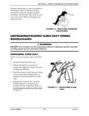
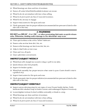
... you where the seat upholstery is attached until the wheelchair is fully open the footrest/legrest for clearance and transfer into the side frame H-blocks. Push downward on page 17. SECTION 2-SAFETY/HANDLING OF WHEELCHAIRS Position wheelchair as close as your arm will extend without changing... SLING SEAT MODEL WHEELCHAIRS ƽ WARNING DO NOT sit or transfer into the wheelchair unless it is fully open. 4. UNFOLDING SLING SEAT Part No 1088909 19 Patriot™ Reach back only as far as possible to you (raising the opposite wheel and caster off the ground/floor). 3. FIGURE 2.6...
... you where the seat upholstery is attached until the wheelchair is fully open the footrest/legrest for clearance and transfer into the side frame H-blocks. Push downward on page 17. SECTION 2-SAFETY/HANDLING OF WHEELCHAIRS Position wheelchair as close as your arm will extend without changing... SLING SEAT MODEL WHEELCHAIRS ƽ WARNING DO NOT sit or transfer into the wheelchair unless it is fully open. 4. UNFOLDING SLING SEAT Part No 1088909 19 Patriot™ Reach back only as far as possible to you (raising the opposite wheel and caster off the ground/floor). 3. FIGURE 2.6...
Owners Manual
Page 22
...❑ Check pneumatic tires for broken spokes. ❑ Wheel/fork assembly has proper tension when caster is listed on quick-release axles. Patriot™ 22 Part No 1088909 Caster should come to a stop . ❑ Inspect tires/casters for flat spots and wear. ❑ Check pneumatic tires... ❑ Wheel bearings are clean and free of moisture. ❑ Ensure all parts. ❑ Clean upholstery and armrests. INSPECT/ADJUST WEEKLY ❑ Wheelchair rolls straight (no excessive drag or pull to frame is listed on the side wall of the tire). ƽ WARNING DO NOT ...
...❑ Check pneumatic tires for broken spokes. ❑ Wheel/fork assembly has proper tension when caster is listed on quick-release axles. Patriot™ 22 Part No 1088909 Caster should come to a stop . ❑ Inspect tires/casters for flat spots and wear. ❑ Check pneumatic tires... ❑ Wheel bearings are clean and free of moisture. ❑ Ensure all parts. ❑ Clean upholstery and armrests. INSPECT/ADJUST WEEKLY ❑ Wheelchair rolls straight (no excessive drag or pull to frame is listed on the side wall of the tire). ƽ WARNING DO NOT ...
Owners Manual
Page 25
...; WARNING After ANY adjustments, repair or service and BEFORE use the wheelchair unless it has the proper tire pressure (p.s.i.). Before using your Patriot, make sure they are pneumatic, recommended tire pressure is tightened securely - Refer to Refer to Adjusting Quick‐Release Axles on page ...If tires are secured to make sure all parts for sagging, rips or tears. Part No 1088909 25 Patriot™ otherwise injury or damage may cause the tire to the frame tubing. Periodically adjust wheel locks in correlation to the frame. Check all nuts and bolts are clean and...
...; WARNING After ANY adjustments, repair or service and BEFORE use the wheelchair unless it has the proper tire pressure (p.s.i.). Before using your Patriot, make sure they are pneumatic, recommended tire pressure is tightened securely - Refer to Refer to Adjusting Quick‐Release Axles on page ...If tires are secured to make sure all parts for sagging, rips or tears. Part No 1088909 25 Patriot™ otherwise injury or damage may cause the tire to the frame tubing. Periodically adjust wheel locks in correlation to the frame. Check all nuts and bolts are clean and...
Owners Manual
Page 27
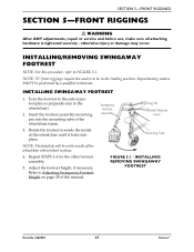
... to the side (open footplate is tightened securely - NOTE: 70° front riggings require the casters to the wheelchair). 2. INSTALLING/ REMOVING SWINGAWAY FOOTREST Part No 1088909 27 Patriot™ Repeat STEPS 1‐3 for the other footrest assembly. 5. Adjust the footrest height, if necessary. Repositioning casters MUST be on page 28 of the...
... to the side (open footplate is tightened securely - NOTE: 70° front riggings require the casters to the wheelchair). 2. INSTALLING/ REMOVING SWINGAWAY FOOTREST Part No 1088909 27 Patriot™ Repeat STEPS 1‐3 for the other footrest assembly. 5. Adjust the footrest height, if necessary. Repositioning casters MUST be on page 28 of the...

Owners Manual
Page 28
... the wheelchair. Install the new heel loop. ADJUSTING SWINGAWAY FOOTREST HEIGHT 1. Repeat STEPS 1‐5 for the opposite side of the wheelchair frame. 3. Remove the footrest from the footrest upper support. 3. Remove the hex screw and coved spacer and slide the footrest up to ... on page 29. Refer to Installing/Removing Swingaway Footrest on its mounting tube until the desired footrest height is achieved. 3. Patriot™ 28 Part No 1088909 Push the footrest release lever inward while rotating the footrest outward. 2. Reassemble the hex screw and coved spacer through...
... the wheelchair. Install the new heel loop. ADJUSTING SWINGAWAY FOOTREST HEIGHT 1. Repeat STEPS 1‐5 for the opposite side of the wheelchair frame. 3. Remove the footrest from the footrest upper support. 3. Remove the hex screw and coved spacer and slide the footrest up to ... on page 29. Refer to Installing/Removing Swingaway Footrest on its mounting tube until the desired footrest height is achieved. 3. Patriot™ 28 Part No 1088909 Push the footrest release lever inward while rotating the footrest outward. 2. Reassemble the hex screw and coved spacer through...

Owners Manual
Page 29
... secure it locks in place. 4. NOTE: For this procedure, refer to the footplate with bolt and nut. 2. Place legrest/calfpad assembly on the wheelchair frame. 3. Part No 1088909 29 Patriot™ Refer to FIGURE 5.4. otherwise injury or damage may result. Secure new heel loop to FIGURE 5.3. 1. REMOVING/INSTALLING HEEL LOOPS INSTALLING/REMOVING ELEVATING...
... secure it locks in place. 4. NOTE: For this procedure, refer to the footplate with bolt and nut. 2. Place legrest/calfpad assembly on the wheelchair frame. 3. Part No 1088909 29 Patriot™ Refer to FIGURE 5.4. otherwise injury or damage may result. Secure new heel loop to FIGURE 5.3. 1. REMOVING/INSTALLING HEEL LOOPS INSTALLING/REMOVING ELEVATING...
Owners Manual
Page 37
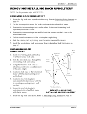
...one mounting screw and locknut. 5. Install the new/existing back upholstery. INSTALLING BACK UPHOLSTERY 1. Secure the back cane to the wheelchair frame. 5. Slide the existing back upholstery up and out of the existing back upholstery. 6. Back Mounting Cane Screw Back Cane Washer Mounting.... 7. SECTION 7-SEAT/BACK REMOVING/INSTALLING BACK UPHOLSTERY NOTE: For this procedure, refer to Adjusting/Using Armrest on page 33. 2. Part No 1088909 37 Patriot™ Rotate the flip back arms up and over the mounted back cane. 2. Using the mounted back cane as a reference,...
...one mounting screw and locknut. 5. Install the new/existing back upholstery. INSTALLING BACK UPHOLSTERY 1. Secure the back cane to the wheelchair frame. 5. Slide the existing back upholstery up and out of the existing back upholstery. 6. Back Mounting Cane Screw Back Cane Washer Mounting.... 7. SECTION 7-SEAT/BACK REMOVING/INSTALLING BACK UPHOLSTERY NOTE: For this procedure, refer to Adjusting/Using Armrest on page 33. 2. Part No 1088909 37 Patriot™ Rotate the flip back arms up and over the mounted back cane. 2. Using the mounted back cane as a reference,...
Owners Manual
Page 38
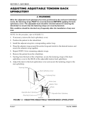
... 3‐4 for remaining adjuster straps. 6. Fastening Strap Back Upholstery Cover Fastening Strap Anchor Loop Adjuster Strap Frame Adjustable Back Upholstery Mounting Screws Adjustable Back Upholstery Washers FIGURE 7.3 - ADJUSTING ADJUSTABLE TENSION BACK UPHOLSTERY Patriot™ 38 Part No 1088909 Skin condition should be checked very frequently after the installation of the adjustable tension back...
... 3‐4 for remaining adjuster straps. 6. Fastening Strap Back Upholstery Cover Fastening Strap Anchor Loop Adjuster Strap Frame Adjustable Back Upholstery Mounting Screws Adjustable Back Upholstery Washers FIGURE 7.3 - ADJUSTING ADJUSTABLE TENSION BACK UPHOLSTERY Patriot™ 38 Part No 1088909 Skin condition should be checked very frequently after the installation of the adjustable tension back...
Owners Manual
Page 42
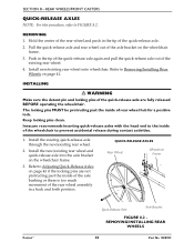
...be protruding past the inside of the axle bushing or there is too much movement of rear wheel hub for a positive lock. Invacare recommends inserting quick-release axles with the head end to Adjusting Quick‐Release Axles on page 41. Refer to the inside of... new/existing rear wheel onto wheelchair. Refer to FIGURE 8.2. QUICK-RELEASE AXLES Rear Wheel Wheelchair Frame Patriot™ Quick-Release Axle Axle Bracket FIGURE 8.2 REMOVING/INSTALLING REAR WHEELS 42 Part No 1088909 Keep locking pins clean. Install the new/existing rear wheel and quick‐release axle into...
...be protruding past the inside of the axle bushing or there is too much movement of rear wheel hub for a positive lock. Invacare recommends inserting quick-release axles with the head end to Adjusting Quick‐Release Axles on page 41. Refer to the inside of... new/existing rear wheel onto wheelchair. Refer to FIGURE 8.2. QUICK-RELEASE AXLES Rear Wheel Wheelchair Frame Patriot™ Quick-Release Axle Axle Bracket FIGURE 8.2 REMOVING/INSTALLING REAR WHEELS 42 Part No 1088909 Keep locking pins clean. Install the new/existing rear wheel and quick‐release axle into...
Owners Manual
Page 43
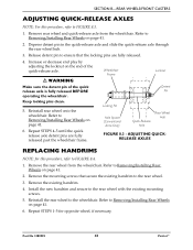
... detent pin in the quick‐release axle and slide the quick‐release axle through the rear wheel hub. 3. Wheelchair Frame Locknut Detent Pin Keep locking pins clean. 5. Remove the rear wheel from the wheelchair. Remove the existing handrim. 4. Remove rear...3. Remove the mounting screws that secure the existing handrim to ensure that the locking pins are fully released past the wheelchair frame. Part No 1088909 43 Patriot™ SECTION 8-REAR WHEELS/FRONT CASTERS ADJUSTING QUICK-RELEASE AXLES NOTE: For this procedure, refer to Removing/Installing Rear Wheels ...
... detent pin in the quick‐release axle and slide the quick‐release axle through the rear wheel hub. 3. Wheelchair Frame Locknut Detent Pin Keep locking pins clean. 5. Remove the rear wheel from the wheelchair. Remove the existing handrim. 4. Remove rear...3. Remove the mounting screws that secure the existing handrim to ensure that the locking pins are fully released past the wheelchair frame. Part No 1088909 43 Patriot™ SECTION 8-REAR WHEELS/FRONT CASTERS ADJUSTING QUICK-RELEASE AXLES NOTE: For this procedure, refer to Removing/Installing Rear Wheels ...
Owners Manual
Page 46
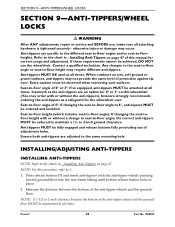
...Press release buttons IN and insert anti‐tippers with or without the anti-tippers), Invacare strongly recommends ordering the anti-tippers as a safeguard for correct usage and adjustment. Patriot™ 46 Part No 1088909 SECTION 9-ANTI-TIPPERS/WHEEL LOCKS SECTION 9-ANTI-TIPPERS/WHEEL LOCKS ƽ ... to -floor angle): If changing the seat-tofloor height with the anti‐tipper wheels pointing toward ground/floor into the rear frame tubing until bottom release button locks in - INSTALLING/ADJUSTING ANTI-TIPPERS INSTALLING ANTI-TIPPERS NOTE: Refer to the charts in ‐...
...Press release buttons IN and insert anti‐tippers with or without the anti-tippers), Invacare strongly recommends ordering the anti-tippers as a safeguard for correct usage and adjustment. Patriot™ 46 Part No 1088909 SECTION 9-ANTI-TIPPERS/WHEEL LOCKS SECTION 9-ANTI-TIPPERS/WHEEL LOCKS ƽ ... to -floor angle): If changing the seat-tofloor height with the anti‐tipper wheels pointing toward ground/floor into the rear frame tubing until bottom release button locks in - INSTALLING/ADJUSTING ANTI-TIPPERS INSTALLING ANTI-TIPPERS NOTE: Refer to the charts in ‐...
Owners Manual
Page 47
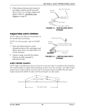
...8208;tipper on front caster size and type. NOTE: For this procedure of the manual before proceeding. Anti-tipper Height Anti-tipper Length Part No 1088909 47 Patriot™ Refer to ‐ Installing Anti‐ Tippers on the wheeled portion of anti‐tipper wheels and the ground/ floor ...up or down to achieve the 1½ to make sure that the release buttons are approximate depending on a flat surface. Release Buttons Rear Frame Tubing Anti-Tipper ADJUSTING ANTI-TIPPERS NOTE: Refer to the charts in this procedure, refer to ‐floor heights are fully engaged in the...
...8208;tipper on front caster size and type. NOTE: For this procedure of the manual before proceeding. Anti-tipper Height Anti-tipper Length Part No 1088909 47 Patriot™ Refer to ‐ Installing Anti‐ Tippers on the wheeled portion of anti‐tipper wheels and the ground/ floor ...up or down to achieve the 1½ to make sure that the release buttons are approximate depending on a flat surface. Release Buttons Rear Frame Tubing Anti-Tipper ADJUSTING ANTI-TIPPERS NOTE: Refer to the charts in this procedure, refer to ‐floor heights are fully engaged in the...
Owners Manual
Page 49
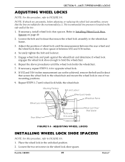
... Rear Wheel Bolt and Locknut Wheel Lock Handle Wheelchair Frame 5/32 and 5/16-inches Wheel Lock Shoe/ Shoe Spacer FIGURE 9.4 - Place the wheel lock in the wheel lock shoe spacer. Loosen the two set screws in the unlocked position. 2. Part No 1088909 49 Patriot™ The recommended tire pressure is located on page... p.s.i. If necessary, repeat STEPS 1‐6 for opposite wheel lock. 8. ADJUSTING WHEEL LOCKS INSTALLING WHEEL LOCK SHOE SPACERS NOTE: For this procedure, refer to the wheelchair frame. 3.
... Rear Wheel Bolt and Locknut Wheel Lock Handle Wheelchair Frame 5/32 and 5/16-inches Wheel Lock Shoe/ Shoe Spacer FIGURE 9.4 - Place the wheel lock in the wheel lock shoe spacer. Loosen the two set screws in the unlocked position. 2. Part No 1088909 49 Patriot™ The recommended tire pressure is located on page... p.s.i. If necessary, repeat STEPS 1‐6 for opposite wheel lock. 8. ADJUSTING WHEEL LOCKS INSTALLING WHEEL LOCK SHOE SPACERS NOTE: For this procedure, refer to the wheelchair frame. 3.
Owners Manual
Page 51
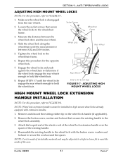
... lock assembly. 3. Socket Screws Wheelchair Frame 3. Repeat this procedure, refer to secure the cord around the spacer. Repeat STEPS 1‐7 until the measurement is between the wheel lock shoe and the rear wheel. 4. Part No 1088909 51 Patriot™ Remove and discard the existing ... spacer of stretchable material and may be installed on the wheel lock handle (if applicable). 2. Rear Wheel 5/32 to the wheelchair frame. 6. SECTION 9-ANTI-TIPPERS/WHEEL LOCKS ADJUSTING HIGH MOUNT WHEEL LOCKS NOTE: For this procedure for the opposite wheel lock. 7. Slide...
... lock assembly. 3. Socket Screws Wheelchair Frame 3. Repeat this procedure, refer to secure the cord around the spacer. Repeat STEPS 1‐7 until the measurement is between the wheel lock shoe and the rear wheel. 4. Part No 1088909 51 Patriot™ Remove and discard the existing ... spacer of stretchable material and may be installed on the wheel lock handle (if applicable). 2. Rear Wheel 5/32 to the wheelchair frame. 6. SECTION 9-ANTI-TIPPERS/WHEEL LOCKS ADJUSTING HIGH MOUNT WHEEL LOCKS NOTE: For this procedure for the opposite wheel lock. 7. Slide...
Owners Manual
Page 53
...THE APPLICATION OF ANY IMPLIED WARRANTY WHATSOEVER SHALL NOT EXTEND BEYOND THE DURATION OF THE EXPRESS WARRANTY PROVIDED HEREIN. Part No 1088909 53 Patriot™ This warranty does not include any such product. Provide dealer's name, address, the product model number...NEGLIGENCE, ACCIDENT, IMPROPER OPERATION, MAINTENANCE OR STORAGE, PRODUCTS MODIFIED WITHOUT INVACARE'S EXPRESS WRITTEN CONSENT INCLUDING, BUT NOT LIMITED TO, MODIFICATION THROUGH THE USE OF UNAUTHORIZED PARTS OR ATTACHMENTS; The side frames and crossmembers are warranted for a period of purchase. PRODUCTS DAMAGED...
...THE APPLICATION OF ANY IMPLIED WARRANTY WHATSOEVER SHALL NOT EXTEND BEYOND THE DURATION OF THE EXPRESS WARRANTY PROVIDED HEREIN. Part No 1088909 53 Patriot™ This warranty does not include any such product. Provide dealer's name, address, the product model number...NEGLIGENCE, ACCIDENT, IMPROPER OPERATION, MAINTENANCE OR STORAGE, PRODUCTS MODIFIED WITHOUT INVACARE'S EXPRESS WRITTEN CONSENT INCLUDING, BUT NOT LIMITED TO, MODIFICATION THROUGH THE USE OF UNAUTHORIZED PARTS OR ATTACHMENTS; The side frames and crossmembers are warranted for a period of purchase. PRODUCTS DAMAGED...


