User Guide
Page 2
...or nonoperating limits. It is the responsibility of the system integrator that need adequate airflow for any express or implied warranty, relating to sale and/or use Intel developed server building blocks to consult vendor datasheets and operating parameters ...Intel's own chassis are trademarks or registered trademarks of Intel Corporation or its subsidiaries in connection with Intel® products. All Rights Reserved ii Intel may occur. Copyright © 2004-2006, Intel Corporation. Intel server boards contain a number of these components when the fully integrated system...
...or nonoperating limits. It is the responsibility of the system integrator that need adequate airflow for any express or implied warranty, relating to sale and/or use Intel developed server building blocks to consult vendor datasheets and operating parameters ...Intel's own chassis are trademarks or registered trademarks of Intel Corporation or its subsidiaries in connection with Intel® products. All Rights Reserved ii Intel may occur. Copyright © 2004-2006, Intel Corporation. Intel server boards contain a number of these components when the fully integrated system...

User Guide
Page 3
... components and their locations. This manual is compatible with the following Intel® Server Boards and Platforms: Intel® Server Board SE7520JR2 Intel® Server Board SE7320VP2 Intel® Server Platform SR2400SYS (integrated system) Intel® Server Platform SR2400SYSD2 (integrated system) 1 For complete technical specifications and additional technical information, see the Intel® Server Chassis SR2400/SR2400DC Technical Product Specification. Manual Organization Chapter 1 provides a brief...
... components and their locations. This manual is compatible with the following Intel® Server Boards and Platforms: Intel® Server Board SE7520JR2 Intel® Server Board SE7320VP2 Intel® Server Platform SR2400SYS (integrated system) Intel® Server Platform SR2400SYSD2 (integrated system) 1 For complete technical specifications and additional technical information, see the Intel® Server Chassis SR2400/SR2400DC Technical Product Specification. Manual Organization Chapter 1 provides a brief...

User Guide
Page 4
... installed in the chassis Low-profile PCI-X riser, installed in the chassis CD-ROM / DVD drive tray, installed in the chassis Four system fans, installed in the chassis Chassis intrusion switch, installed in the chassis Air baffle, installed in the chassis Processor air duct, installed in ...box Rack handles, in the hardware box Quick Start User's Guide, in the chassis box Attention document, in the Intel Server Platform SR2400JR2. 3 Before purchasing any required options, refer to your server board documentation to below as the "hardware box" One 700-W power supply (AC version) or one : ⎯...
... installed in the chassis Low-profile PCI-X riser, installed in the chassis CD-ROM / DVD drive tray, installed in the chassis Four system fans, installed in the chassis Chassis intrusion switch, installed in the chassis Air baffle, installed in the chassis Processor air duct, installed in ...box Rack handles, in the hardware box Quick Start User's Guide, in the chassis box Attention document, in the Intel Server Platform SR2400JR2. 3 Before purchasing any required options, refer to your server board documentation to below as the "hardware box" One 700-W power supply (AC version) or one : ⎯...
User Guide
Page 5
... or more of the following items for your server: 5 Server rack cabinet and rails / brackets to mount the server into a rack Cable management arm Front bezel for the selected control panel option Processor(s) and heat sink(s) Memory DIMMs Intel® Management Module (Advanced or Professional) Tape...been tested and can be used with your chassis, and for ordering information for Intel products, see http://www.support.intel.com/support/motherboards/server/chassis/SR2400/ 5 Before purchasing any optional items, refer to your server board documentation to determine which items are supported on your...
... or more of the following items for your server: 5 Server rack cabinet and rails / brackets to mount the server into a rack Cable management arm Front bezel for the selected control panel option Processor(s) and heat sink(s) Memory DIMMs Intel® Management Module (Advanced or Professional) Tape...been tested and can be used with your chassis, and for ordering information for Intel products, see http://www.support.intel.com/support/motherboards/server/chassis/SR2400/ 5 Before purchasing any optional items, refer to your server board documentation to determine which items are supported on your...

User Guide
Page 6
... available at the left side of the screen Accessories or other Intel server products Search for "Spares and Configuration Guide" Hardware (peripheral boards, adapter cards) and operating systems that have been tested with this product Search for "Tested Hardware and Operating System List" Server boards that have been tested with this product Search for "Compatible...
... available at the left side of the screen Accessories or other Intel server products Search for "Spares and Configuration Guide" Hardware (peripheral boards, adapter cards) and operating systems that have been tested with this product Search for "Tested Hardware and Operating System List" Server boards that have been tested with this product Search for "Compatible...

User Guide
Page 7
... rear of the product and will void the UL listing and other resource as controlling power to the system. Grounding the Server (Intel® Server Chassis SR2400DC only) To avoid the potential for the system. Preface Safety Information WARNING Before working with your server product, whether you must reliably connect an earth-grounding conductor to the...
... rear of the product and will void the UL listing and other resource as controlling power to the system. Grounding the Server (Intel® Server Chassis SR2400DC only) To avoid the potential for the system. Preface Safety Information WARNING Before working with your server product, whether you must reliably connect an earth-grounding conductor to the...

User Guide
Page 8
...causing intermittent problems with , but not the board wrapper. Turn off the system AC or DC power. Do not slide board over two jumper pins. After removing a board from its protective wrapper or from the server, place the board component side up on your jumpers do not have a ... discharge (ESD) and ESD protection: ESD can be present on /off: The power button DOES NOT turn off the server and disconnect the power cord, telecommunications systems, networks, and modems attached to chassis ground⎯any components. Hold boards only by that you must unplug the AC power...
...causing intermittent problems with , but not the board wrapper. Turn off the system AC or DC power. Do not slide board over two jumper pins. After removing a board from its protective wrapper or from the server, place the board component side up on your jumpers do not have a ... discharge (ESD) and ESD protection: ESD can be present on /off: The power button DOES NOT turn off the server and disconnect the power cord, telecommunications systems, networks, and modems attached to chassis ground⎯any components. Hold boards only by that you must unplug the AC power...

User Guide
Page 9
... in this product contains no user-serviceable parts. See also Intel Server Boards and Server Chassis Safety Information at http://support.intel.com/support/motherboards/server/sb/CS-010770.htm. Turn off system AC power. There may be easily accessible. The socket outlet that the system plugs into shall be installed near the equipment and shall be...
... in this product contains no user-serviceable parts. See also Intel Server Boards and Server Chassis Safety Information at http://support.intel.com/support/motherboards/server/sb/CS-010770.htm. Turn off system AC power. There may be easily accessible. The socket outlet that the system plugs into shall be installed near the equipment and shall be...
User Guide
Page 19
... / CD-ROM / DVD-ROM Drives 10 Tape Drive...10 Advanced Management Options 11 Intel® Management Module 11 Rack-Mounted Systems ...11 Front Bezels ...11 2 Hardware Installations and Upgrades 13 Before You Begin ...13 Tools and Supplies Needed 13 System References ...13 Removing and Installing the Chassis Cover 14 Removing the Chassis Cover... Fan Module 28 Installing the Fan Module 29 Installing and Removing a Hard Disk Drive 31 Removing a SATA or SCSI Hot-swap Hard Disk Drive 31 Intel® Server Chassis SR2400/SR2400DC User Guide xix
... / CD-ROM / DVD-ROM Drives 10 Tape Drive...10 Advanced Management Options 11 Intel® Management Module 11 Rack-Mounted Systems ...11 Front Bezels ...11 2 Hardware Installations and Upgrades 13 Before You Begin ...13 Tools and Supplies Needed 13 System References ...13 Removing and Installing the Chassis Cover 14 Removing the Chassis Cover... Fan Module 28 Installing the Fan Module 29 Installing and Removing a Hard Disk Drive 31 Removing a SATA or SCSI Hot-swap Hard Disk Drive 31 Intel® Server Chassis SR2400/SR2400DC User Guide xix

User Guide
Page 21
...6 Figure 6. Installing the Processor Air Dam 20 Figure 16. Removing the Small Hot-swap Air Baffle 24 Intel® Server Chassis SR2400/SR2400DC User Guide xxi Intel® Server Chassis SR2400/SR2400DC 1 Figure 2. Optional Peripherals ...9 Figure 9. Installing the Large Hot-swap Air Baffle 23... (Japan)...105 BSMI (Taiwan)...105 Korean RRL Compliance 105 Regulated Specified Components 106 Intel® Server Issue Report Form 109 Warranty...113 Limited Warranty for Intel® Chassis Subassembly Products 113 Extent of Limited Warranty 113 Warranty Limitations and Exclusions...
...6 Figure 6. Installing the Processor Air Dam 20 Figure 16. Removing the Small Hot-swap Air Baffle 24 Intel® Server Chassis SR2400/SR2400DC User Guide xxi Intel® Server Chassis SR2400/SR2400DC 1 Figure 2. Optional Peripherals ...9 Figure 9. Installing the Large Hot-swap Air Baffle 23... (Japan)...105 BSMI (Taiwan)...105 Korean RRL Compliance 105 Regulated Specified Components 106 Intel® Server Issue Report Form 109 Warranty...113 Limited Warranty for Intel® Chassis Subassembly Products 113 Extent of Limited Warranty 113 Warranty Limitations and Exclusions...

User Guide
Page 22
... Installing a Floppy Drive into the Floppy Drive Conversion Kit Carrier 54 Figure 48. Connecting the Floppy Drive Cables 51 Figure 46. Installing a System Fan 71 Figure 63. Installing the Fixed Drive Air Baffle 27 Figure 22. Attaching a Hot-swap Hard Disk Drive to a Floppy Drive 49...Carrier 37 Figure 33. Connecting the Flat Flex Cable to the Fixed Drive Carrier 37 Figure 34. Removing the Retention Device from the Server Board 73 Figure 64. Removing the Power Distribution Module 75 xxii Installing the Floppy Drive into the Slimline Carrier 58 Figure 53. Installing...
... Installing a Floppy Drive into the Floppy Drive Conversion Kit Carrier 54 Figure 48. Connecting the Floppy Drive Cables 51 Figure 46. Installing a System Fan 71 Figure 63. Installing the Fixed Drive Air Baffle 27 Figure 22. Attaching a Hot-swap Hard Disk Drive to a Floppy Drive 49...Carrier 37 Figure 33. Connecting the Flat Flex Cable to the Fixed Drive Carrier 37 Figure 34. Removing the Retention Device from the Server Board 73 Figure 64. Removing the Power Distribution Module 75 xxii Installing the Floppy Drive into the Slimline Carrier 58 Figure 53. Installing...
User Guide
Page 23
... 87 Figure 78. Installing the Filler Panels 93 Tables Table 1. Table 3. Removing a Hot-swap Power Supply 85 Figure 77. Server Chassis Features 2 Product Certification Markings 102 Product Certification Markings 103 Intel® Server Chassis SR2400/SR2400DC User Guide xxiii Installing a SATA or SCSI Backplane 88 Figure 79. Removing the Tape Drive Bay Filler...
... 87 Figure 78. Installing the Filler Panels 93 Tables Table 1. Table 3. Removing a Hot-swap Power Supply 85 Figure 77. Server Chassis Features 2 Product Certification Markings 102 Product Certification Markings 103 Intel® Server Chassis SR2400/SR2400DC User Guide xxiii Installing a SATA or SCSI Backplane 88 Figure 79. Removing the Tape Drive Bay Filler...

User Guide
Page 25
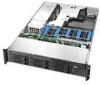
The Intel® Server Chassis SR2400/SR2400DC is shown in the following picture. This chapter provides pictures of the product, a list of the server features, and diagrams showing the location of Intel® Server Chassis SR2400/SR2400DC. Figure 1. Server Chassis Features 1 Server Chassis Features This chapter briefly describes the main features of important components and connections on the server chassis. Intel® Server Chassis SR2400/SR2400DC Intel® Server Chassis SR2400/SR2400DC User Guide 1
The Intel® Server Chassis SR2400/SR2400DC is shown in the following picture. This chapter provides pictures of the product, a list of the server features, and diagrams showing the location of Intel® Server Chassis SR2400/SR2400DC. Figure 1. Server Chassis Features 1 Server Chassis Features This chapter briefly describes the main features of important components and connections on the server chassis. Intel® Server Chassis SR2400/SR2400DC Intel® Server Chassis SR2400/SR2400DC User Guide 1
User Guide
Page 26
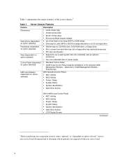
... fans in power supply Control Panel (dependent on option selected," refer to your server board documentation to eight system fans (four standard, four as either "optional,"or "dependent on option selected) Standard Control Panel Intel® Local Control Panel (requires installation of the server chassis.6 Table 1. Table 1 summarizes the major features of the optional...
... fans in power supply Control Panel (dependent on option selected," refer to your server board documentation to eight system fans (four standard, four as either "optional,"or "dependent on option selected) Standard Control Panel Intel® Local Control Panel (requires installation of the server chassis.6 Table 1. Table 1 summarizes the major features of the optional...
User Guide
Page 27
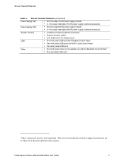
Intel® Server Chassis SR2400/SR2400DC User Guide 3 Server Chassis Features Table 1. The server board and chassis do not support synchronous use of video out of the front and back of the chassis. Server Chassis Features (continued) Power Supply (AC) One hot-swap 700-W power supply module 1+1 ...600-W power supply (optional accessory) System Security Lockable front bezel (optional accessory) Chassis intrusion switch Lock attach point for chassis cover USB One front panel USB port with Standard Control Panel Two front panel USB ports with Intel® Local Control Panel Two ...
Intel® Server Chassis SR2400/SR2400DC User Guide 3 Server Chassis Features Table 1. The server board and chassis do not support synchronous use of video out of the front and back of the chassis. Server Chassis Features (continued) Power Supply (AC) One hot-swap 700-W power supply module 1+1 ...600-W power supply (optional accessory) System Security Lockable front bezel (optional accessory) Chassis intrusion switch Lock attach point for chassis cover USB One front panel USB port with Standard Control Panel Two front panel USB ports with Intel® Local Control Panel Two ...
User Guide
Page 29
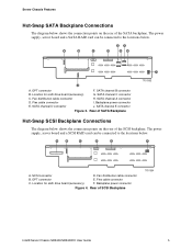
... shows the connection points on the rear of the SCSI backplane. Location for sixth drive board (accessory) G. The power supply, server board and a SATA RAID card can be connected to the locations below . Location for sixth drive board (accessory) F. A B C ...D E F A. Rear of SCSI Backplane TP01364 Intel® Server Chassis SR2400/SR2400DC User Guide 5 Server Chassis Features Hot-Swap SATA Backplane Connections The diagram below shows the connection points on the rear of the SATA backplane....
... shows the connection points on the rear of the SCSI backplane. Location for sixth drive board (accessory) G. The power supply, server board and a SATA RAID card can be connected to the locations below . Location for sixth drive board (accessory) F. A B C ...D E F A. Rear of SCSI Backplane TP01364 Intel® Server Chassis SR2400/SR2400DC User Guide 5 Server Chassis Features Hot-Swap SATA Backplane Connections The diagram below shows the connection points on the rear of the SATA backplane....

User Guide
Page 30
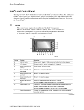
... chassis and allows you to locate the server from the rear of a rack of the chassis. Standard Control Panel 6 Random blinking green light indicates hard disk drive activity (SCSI or SATA). Solid blue indicates system identification is the Intel® Local Control Panel. Toggles the ...button Video port L KJ TP00779 Function Blinking green light indicates network activity. No light indicates POST is running or the system is off / is connected. Puts the server in S1 sleep state. No light indicates no hard disk drive activity. Allows you to attach a video monitor to...
... chassis and allows you to locate the server from the rear of a rack of the chassis. Standard Control Panel 6 Random blinking green light indicates hard disk drive activity (SCSI or SATA). Solid blue indicates system identification is the Intel® Local Control Panel. Toggles the ...button Video port L KJ TP00779 Function Blinking green light indicates network activity. No light indicates POST is running or the system is off / is connected. Puts the server in S1 sleep state. No light indicates no hard disk drive activity. Allows you to attach a video monitor to...
User Guide
Page 31
...attach a USB component to the previous page. Continuous green light indicates the system has power applied to the previous option. Sleep button for ACPI-compatible operating systems. Continued Intel® Server Chassis SR2400/SR2400DC User Guide 7 No light indicates the power is off... scroll left Menu control button, scroll right System Identification LED H Power/Sleep LED I H G TP00780 Callout A B C D E F G Feature USB 2.0 ports LCD display Menu control button, scroll up one of the chassis. Server Chassis Features Intel® Local Control Panel The diagram below ...
...attach a USB component to the previous page. Continuous green light indicates the system has power applied to the previous option. Sleep button for ACPI-compatible operating systems. Continued Intel® Server Chassis SR2400/SR2400DC User Guide 7 No light indicates the power is off... scroll left Menu control button, scroll right System Identification LED H Power/Sleep LED I H G TP00780 Callout A B C D E F G Feature USB 2.0 ports LCD display Menu control button, scroll up one of the chassis. Server Chassis Features Intel® Local Control Panel The diagram below ...
User Guide
Page 32
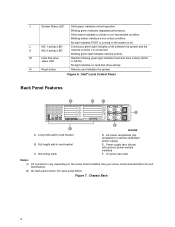
.... Grounding studs E AF00638 D. Intel® Local Control Panel Back Panel Features A B C D F A. AC power receptacles (top receptacle for port identification. (2) AC back panel shown; No light indicates POST is running or the system is connected. Figure 6. DC ... disk drive activity. See your server board documentation for optional redundant power supply) E. Figure 7. Blinking green indicates degraded performance. Chassis Back 8 I/O ports (see note) Notes: (1) I/O connectors vary, depending on the server board installed. Low-profile add-in...
.... Grounding studs E AF00638 D. Intel® Local Control Panel Back Panel Features A B C D F A. AC power receptacles (top receptacle for port identification. (2) AC back panel shown; No light indicates POST is running or the system is connected. Figure 6. DC ... disk drive activity. See your server board documentation for optional redundant power supply) E. Figure 7. Blinking green indicates degraded performance. Chassis Back 8 I/O ports (see note) Notes: (1) I/O connectors vary, depending on the server board installed. Low-profile add-in...
User Guide
Page 33
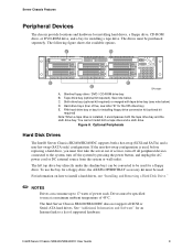
...Serial ATA hard drives. To use the bay for the fifth drive bay) E. The Intel Server Chassis SR2400/SR2400DC does not support all peripheral devices connected to the system, turn off the system by pressing the power button, and unplug the AC power cord or DC external source ... figure shows the available options. See note below ) D. Hard drive bays (four of power each. Figure 8. Optional Peripherals Hard Disk Drives The Intel® Server Chassis SR2400/SR2400DC supports both a tape drive and a sixth drive. For information on how to install a hard drives, see "Installing and Removing ...
...Serial ATA hard drives. To use the bay for the fifth drive bay) E. The Intel Server Chassis SR2400/SR2400DC does not support all peripheral devices connected to the system, turn off the system by pressing the power button, and unplug the AC power cord or DC external source ... figure shows the available options. See note below ) D. Hard drive bays (four of power each. Figure 8. Optional Peripherals Hard Disk Drives The Intel® Server Chassis SR2400/SR2400DC supports both a tape drive and a sixth drive. For information on how to install a hard drives, see "Installing and Removing ...

