User Guide
Page 2
... a situation where personal injury or death may make changes to meet the intended thermal requirements of these components when the fully integrated system is used outside any of their specific application and environmental conditions. Intel server boards contain a number of high-density VLSI and power delivery components that chooses not to use of...
... a situation where personal injury or death may make changes to meet the intended thermal requirements of these components when the fully integrated system is used outside any of their specific application and environmental conditions. Intel server boards contain a number of high-density VLSI and power delivery components that chooses not to use of...

User Guide
Page 3
... in this manual, refer to the documentation provided with the following Intel® Server Boards and Platforms: Intel® Server Board SE7520JR2 Intel® Server Board SE7320VP2 Intel® Server Platform SR2400SYS (integrated system) Intel® Server Platform SR2400SYSD2 (integrated system) 1 For complete technical specifications and additional technical information, see the Intel® Server Chassis SR2400/SR2400DC Technical Product Specification. See "Additional Information and Software...
... in this manual, refer to the documentation provided with the following Intel® Server Boards and Platforms: Intel® Server Board SE7520JR2 Intel® Server Board SE7320VP2 Intel® Server Platform SR2400SYS (integrated system) Intel® Server Platform SR2400SYSD2 (integrated system) 1 For complete technical specifications and additional technical information, see the Intel® Server Chassis SR2400/SR2400DC Technical Product Specification. See "Additional Information and Software...

User Guide
Page 4
...the chassis Low-profile PCI-X riser, installed in the chassis CD-ROM / DVD drive tray, installed in the chassis Four system fans, installed in the chassis Chassis intrusion switch, installed in the chassis Air baffle, installed in the chassis Processor air duct...in the Intel Server Platform SR2400JR2. 3 Before purchasing any required options, refer to your server board documentation to determine which option(s) are supported on your server board. 4 The Intel® Local Control Panel requires the installation of the optional Intel® Management Module - Professional or Intel® Management...
...the chassis Low-profile PCI-X riser, installed in the chassis CD-ROM / DVD drive tray, installed in the chassis Four system fans, installed in the chassis Chassis intrusion switch, installed in the chassis Air baffle, installed in the chassis Processor air duct...in the Intel Server Platform SR2400JR2. 3 Before purchasing any required options, refer to your server board documentation to determine which option(s) are supported on your server board. 4 The Intel® Local Control Panel requires the installation of the optional Intel® Management Module - Professional or Intel® Management...
User Guide
Page 5
... of the following items for your server: 5 Server rack cabinet and rails / brackets to mount the server into a rack Cable management arm Front bezel for the selected control panel option Processor(s) and heat sink(s) Memory DIMMs Intel® Management Module (Advanced or ... and for ordering information for Intel products, see http://www.support.intel.com/support/motherboards/server/chassis/SR2400/ 5 Before purchasing any optional items, refer to your server board documentation to determine which items are supported on your server board. Intel® Server Chassis SR2400/SR2400DC User Guide...
... of the following items for your server: 5 Server rack cabinet and rails / brackets to mount the server into a rack Cable management arm Front bezel for the selected control panel option Processor(s) and heat sink(s) Memory DIMMs Intel® Management Module (Advanced or ... and for ordering information for Intel products, see http://www.support.intel.com/support/motherboards/server/chassis/SR2400/ 5 Before purchasing any optional items, refer to your server board documentation to determine which items are supported on your server board. Intel® Server Chassis SR2400/SR2400DC User Guide...

User Guide
Page 6
... If you need to install it For virtual system tours and interactive repair information A link to the SMaRT Tool is available under "Other Resources" at the left side of the screen Accessories or other Intel server products Search for "Spares and Configuration Guide" ...Hardware (peripheral boards, adapter cards) and operating systems that have been tested with this product Search for "Tested Hardware and Operating System List" Server boards that have been tested with ...
... If you need to install it For virtual system tours and interactive repair information A link to the SMaRT Tool is available under "Other Resources" at the left side of the screen Accessories or other Intel server products Search for "Spares and Configuration Guide" ...Hardware (peripheral boards, adapter cards) and operating systems that have been tested with this product Search for "Tested Hardware and Operating System List" Server boards that have been tested with ...

User Guide
Page 7
... to the safety instructions. Grounding the Server (Intel® Server Chassis SR2400DC only) To avoid the potential for an electrical shock hazard, you are responsible for installing a properly rated DC power disconnect for the system. Intel® Server Chassis SR2400/SR2400DC User Guide vii Emissions... your local regional rules and regulations, the final configuration of your local Intel Representative. See "Regulatory and Integration Information" for the system. Main DC Power Disconnect (Intel® Server Chassis SR2400DC) You are using this guide or any other modules have...
... to the safety instructions. Grounding the Server (Intel® Server Chassis SR2400DC only) To avoid the potential for an electrical shock hazard, you are responsible for installing a properly rated DC power disconnect for the system. Intel® Server Chassis SR2400/SR2400DC User Guide vii Emissions... your local regional rules and regulations, the final configuration of your local Intel Representative. See "Regulatory and Integration Information" for the system. Main DC Power Disconnect (Intel® Server Chassis SR2400DC) You are using this guide or any other modules have...

User Guide
Page 8
...ground⎯any components. viii Electrostatic discharge (ESD) and ESD protection: ESD can grip with your server when handling parts. Warnings System power on a grounded, static free surface. To remove power from the server, place the board component side up on /off: The power button DOES NOT turn off the... server and disconnect the power cord, telecommunications systems, networks, and modems attached to remove a jumper, or you perform all procedures in this chapter only at an ESD workstation. If ...
...ground⎯any components. viii Electrostatic discharge (ESD) and ESD protection: ESD can grip with your server when handling parts. Warnings System power on a grounded, static free surface. To remove power from the server, place the board component side up on /off: The power button DOES NOT turn off the... server and disconnect the power cord, telecommunications systems, networks, and modems attached to remove a jumper, or you perform all procedures in this chapter only at an ESD workstation. If ...

User Guide
Page 9
...this document before performing any unpainted metal surface-when handling components. 6. Intel® Server Chassis SR2400/SR2400DC User Guide ix A product with the chassis covers removed. The socket outlet that the system plugs into shall be installed near the equipment and shall be more ...save all AC power cords from the system or from the covers. 3. Preface Safety Cautions Read all caution and safety statements in this : 1. See also Intel Server Boards and Server Chassis Safety Information at http://support.intel.com/support/motherboards/server/sb/CS-010770.htm. The power supply...
...this document before performing any unpainted metal surface-when handling components. 6. Intel® Server Chassis SR2400/SR2400DC User Guide ix A product with the chassis covers removed. The socket outlet that the system plugs into shall be installed near the equipment and shall be more ...save all AC power cords from the system or from the covers. 3. Preface Safety Cautions Read all caution and safety statements in this : 1. See also Intel Server Boards and Server Chassis Safety Information at http://support.intel.com/support/motherboards/server/sb/CS-010770.htm. The power supply...
User Guide
Page 19
... / CD-ROM / DVD-ROM Drives 10 Tape Drive...10 Advanced Management Options 11 Intel® Management Module 11 Rack-Mounted Systems ...11 Front Bezels ...11 2 Hardware Installations and Upgrades 13 Before You Begin ...13 Tools and Supplies Needed 13 System References ...13 Removing and Installing the Chassis Cover 14 Removing the Chassis Cover... Fan Module 28 Installing the Fan Module 29 Installing and Removing a Hard Disk Drive 31 Removing a SATA or SCSI Hot-swap Hard Disk Drive 31 Intel® Server Chassis SR2400/SR2400DC User Guide xix
... / CD-ROM / DVD-ROM Drives 10 Tape Drive...10 Advanced Management Options 11 Intel® Management Module 11 Rack-Mounted Systems ...11 Front Bezels ...11 2 Hardware Installations and Upgrades 13 Before You Begin ...13 Tools and Supplies Needed 13 System References ...13 Removing and Installing the Chassis Cover 14 Removing the Chassis Cover... Fan Module 28 Installing the Fan Module 29 Installing and Removing a Hard Disk Drive 31 Removing a SATA or SCSI Hot-swap Hard Disk Drive 31 Intel® Server Chassis SR2400/SR2400DC User Guide xix

User Guide
Page 21
...CE Declaration of Conformity 104 VCCI (Japan)...105 BSMI (Taiwan)...105 Korean RRL Compliance 105 Regulated Specified Components 106 Intel® Server Issue Report Form 109 Warranty...113 Limited Warranty for Intel® Chassis Subassembly Products 113 Extent of Limited Warranty 113 Warranty Limitations and Exclusions 114 Limitations of Liability 114 ... Returning a Defective Product 115 Figures Figure 1. Internal Component Locations 4 Figure 3. Standard Control Panel 6 Figure 6. Removing the Small Hot-swap Air Baffle 24 Intel® Server Chassis SR2400/SR2400DC User Guide xxi
...CE Declaration of Conformity 104 VCCI (Japan)...105 BSMI (Taiwan)...105 Korean RRL Compliance 105 Regulated Specified Components 106 Intel® Server Issue Report Form 109 Warranty...113 Limited Warranty for Intel® Chassis Subassembly Products 113 Extent of Limited Warranty 113 Warranty Limitations and Exclusions 114 Limitations of Liability 114 ... Returning a Defective Product 115 Figures Figure 1. Internal Component Locations 4 Figure 3. Standard Control Panel 6 Figure 6. Removing the Small Hot-swap Air Baffle 24 Intel® Server Chassis SR2400/SR2400DC User Guide xxi

User Guide
Page 22
...Installing the Floppy Drive Interposer Board 50 Figure 45. Installing the Rails onto the Floppy Drive Conversion Kit Carrier 55 Figure 50. Installing a System Fan 71 Figure 63. Connecting the SCSI Data Cable 35 Figure 31. Installing the Sixth Drive Board 43 Figure 39. Installing a DVD/CDROM...Panel from the Backplane 74 Figure 66. Disconnecting the Power Cable from the Chassis 70 Figure 62. Removing the Retention Device from the Server Board 74 Figure 65. Disconnecting the Power Cables from the Hot-swap Drive Carrier 32 Figure 27. Connecting the Fan Distribution Cable ...
...Installing the Floppy Drive Interposer Board 50 Figure 45. Installing the Rails onto the Floppy Drive Conversion Kit Carrier 55 Figure 50. Installing a System Fan 71 Figure 63. Connecting the SCSI Data Cable 35 Figure 31. Installing the Sixth Drive Board 43 Figure 39. Installing a DVD/CDROM...Panel from the Backplane 74 Figure 66. Disconnecting the Power Cable from the Chassis 70 Figure 62. Removing the Retention Device from the Server Board 74 Figure 65. Disconnecting the Power Cables from the Hot-swap Drive Carrier 32 Figure 27. Connecting the Fan Distribution Cable ...
User Guide
Page 23
Disconnecting the Power Cables from the Backplane 79 Figure 72. Disconnecting the Power Cable from the Server Board 79 Figure 71. Disconnecting the Flex and Power Cables 80 Figure 73. Removing a Hot-swap Power Supply 85 Figure 77. ...90 Figure 81. Table 2. Connecting the Tape Drive Cables 92 Figure 84. Server Chassis Features 2 Product Certification Markings 102 Product Certification Markings 103 Intel® Server Chassis SR2400/SR2400DC User Guide xxiii Disconnecting the Flex Cable from the Server Board 78 Figure 70. Installing a SATA or SCSI Backplane 89 Figure 80....
Disconnecting the Power Cables from the Backplane 79 Figure 72. Disconnecting the Power Cable from the Server Board 79 Figure 71. Disconnecting the Flex and Power Cables 80 Figure 73. Removing a Hot-swap Power Supply 85 Figure 77. ...90 Figure 81. Table 2. Connecting the Tape Drive Cables 92 Figure 84. Server Chassis Features 2 Product Certification Markings 102 Product Certification Markings 103 Intel® Server Chassis SR2400/SR2400DC User Guide xxiii Disconnecting the Flex Cable from the Server Board 78 Figure 70. Installing a SATA or SCSI Backplane 89 Figure 80....

User Guide
Page 25
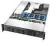
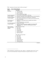
The Intel® Server Chassis SR2400/SR2400DC is shown in the following picture. Intel® Server Chassis SR2400/SR2400DC Intel® Server Chassis SR2400/SR2400DC User Guide 1 Figure 1. This chapter provides pictures of the product, a list of the server features, and diagrams showing the location of Intel® Server Chassis SR2400/SR2400DC. Server Chassis Features 1 Server Chassis Features This chapter briefly describes the main features of important components and connections on the server chassis.
The Intel® Server Chassis SR2400/SR2400DC is shown in the following picture. Intel® Server Chassis SR2400/SR2400DC Intel® Server Chassis SR2400/SR2400DC User Guide 1 Figure 1. This chapter provides pictures of the product, a list of the server features, and diagrams showing the location of Intel® Server Chassis SR2400/SR2400DC. Server Chassis Features 1 Server Chassis Features This chapter briefly describes the main features of important components and connections on the server chassis.
User Guide
Page 26
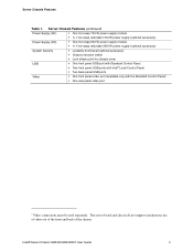
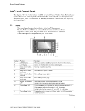
...With Intel® Local Control Panel: NIC1 Activity NIC2 Activity Power / Sleep System Status System Identification Hard Drive Activity LCD Display Screen Continued 6 Before purchasing any component noted as either "optional,"or "dependent on option selected," refer to your server board. 2 Server Chassis ...drive Peripherals (dependent on option selected) Slimline bay for up to determine which option(s) are supported with your server board documentation to eight system fans (four standard, four as optional accessory) Two non-redundant fans in power supply Control Panel (dependent on...
...With Intel® Local Control Panel: NIC1 Activity NIC2 Activity Power / Sleep System Status System Identification Hard Drive Activity LCD Display Screen Continued 6 Before purchasing any component noted as either "optional,"or "dependent on option selected," refer to your server board. 2 Server Chassis ...drive Peripherals (dependent on option selected) Slimline bay for up to determine which option(s) are supported with your server board documentation to eight system fans (four standard, four as optional accessory) Two non-redundant fans in power supply Control Panel (dependent on...
User Guide
Page 27
...not support synchronous use of video out of the front and back of the chassis. Server Chassis Features (continued) Power Supply (AC) One hot-swap 700-W power supply ... One hot-swap 600-W power supply module 1+1 hot-swap redundant 600-W power supply (optional accessory) System Security Lockable front bezel (optional accessory) Chassis intrusion switch Lock attach point for chassis cover USB One front... panel USB port with Standard Control Panel Two front panel USB ports with Intel® Local Control Panel Two back panel USB ports Video One front panel video port (...
...not support synchronous use of video out of the front and back of the chassis. Server Chassis Features (continued) Power Supply (AC) One hot-swap 700-W power supply ... One hot-swap 600-W power supply module 1+1 hot-swap redundant 600-W power supply (optional accessory) System Security Lockable front bezel (optional accessory) Chassis intrusion switch Lock attach point for chassis cover USB One front... panel USB port with Standard Control Panel Two front panel USB ports with Intel® Local Control Panel Two back panel USB ports Video One front panel video port (...
User Guide
Page 29
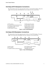
... SCSI Backplane Connections The diagram below shows the connection points on the rear of SCSI Backplane TP01364 Intel® Server Chassis SR2400/SR2400DC User Guide 5 A B C D E F A. SCSI connector D. OPT connector E. Location for sixth drive board... (accessory) G. The power supply, server board and a SCSI RAID card can be connected to the locations below . The power supply, server board and a SATA RAID card can be connected to the locations below . SATA channel B connector...
... SCSI Backplane Connections The diagram below shows the connection points on the rear of SCSI Backplane TP01364 Intel® Server Chassis SR2400/SR2400DC User Guide 5 A B C D E F A. SCSI connector D. OPT connector E. Location for sixth drive board... (accessory) G. The power supply, server board and a SCSI RAID card can be connected to the locations below . The power supply, server board and a SATA RAID card can be connected to the locations below . SATA channel B connector...

User Guide
Page 30
...degraded performance. Allows you to attach a video monitor to it is in a halt-state for ACPI-compatible operating systems. Continuous green light indicates the system has power applied to the front of the chassis. Puts the server in ACPI S4 or S5 state. Continuous green light indicates a link between the... ID LED on /off . No light indicates the power is off . The other option is one of systems. Reboots and initializes the system. The Standard Control Panel is the Intel® Local Control Panel. The baseboard LED is visible from the rear of the chassis and allows you to...
...degraded performance. Allows you to attach a video monitor to it is in a halt-state for ACPI-compatible operating systems. Continuous green light indicates the system has power applied to the front of the chassis. Puts the server in ACPI S4 or S5 state. Continuous green light indicates a link between the... ID LED on /off . No light indicates the power is off . The other option is one of systems. Reboots and initializes the system. The Standard Control Panel is the Intel® Local Control Panel. The baseboard LED is visible from the rear of the chassis and allows you to...
User Guide
Page 31
...up Menu control button, scroll down one option at a time. Solid blue indicates system identification is not activated. Sleep button for ACPI-compatible operating systems. Continued Intel® Server Chassis SR2400/SR2400DC User Guide 7 Scroll down Menu control button, scroll left Menu... control button, scroll right System Identification LED H Power/Sleep LED I H G TP00780 Callout A B C D E F G Feature USB 2.0 ports LCD display Menu control button, scroll up one of the chassis. Server Chassis Features Intel® Local Control Panel The diagram below shows...
...up Menu control button, scroll down one option at a time. Solid blue indicates system identification is not activated. Sleep button for ACPI-compatible operating systems. Continued Intel® Server Chassis SR2400/SR2400DC User Guide 7 Scroll down Menu control button, scroll left Menu... control button, scroll right System Identification LED H Power/Sleep LED I H G TP00780 Callout A B C D E F G Feature USB 2.0 ports LCD display Menu control button, scroll up one of the chassis. Server Chassis Features Intel® Local Control Panel The diagram below shows...
User Guide
Page 32
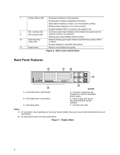
... drive activity. N Reset button Reboots and initializes the system. Figure 6. I/O ports (see note) Notes: (1) I/O connectors vary, depending on the server board installed. Figure 7. No light indicates POST is running or the system is connected. L NIC 1 activity LED Continuous green ...(shown with optional power module installed) F. Chassis Back 8 Low-profile add-in card bracket C. Intel® Local Control Panel Back Panel Features A B C D F A. See your server board documentation for optional redundant power supply) E. DC back panel differs. Solid amber indicates a critical ...
... drive activity. N Reset button Reboots and initializes the system. Figure 6. I/O ports (see note) Notes: (1) I/O connectors vary, depending on the server board installed. Figure 7. No light indicates POST is running or the system is connected. L NIC 1 activity LED Continuous green ...(shown with optional power module installed) F. Chassis Back 8 Low-profile add-in card bracket C. Intel® Local Control Panel Back Panel Features A B C D F A. See your server board documentation for optional redundant power supply) E. DC back panel differs. Solid amber indicates a critical ...
User Guide
Page 33
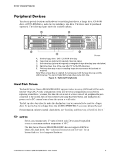
...tape drive. The left top drive bay (directly under the slimline bay) can consume up to 17 watts of five, see note below . The Intel Server Chassis SR2400/SR2400DC does not support all peripheral devices connected to run at a maximum ambient temperature of 45°C. See note below ) D. C. ... encompasses both the tape drive bay and the sixth drive bay. Drives must be specified to the system, turn off the system by pressing the power button, and unplug the AC power cord or DC external source from the system or wall outlet. Intel® Server Chassis SR2400/SR2400DC User Guide 9
...tape drive. The left top drive bay (directly under the slimline bay) can consume up to 17 watts of five, see note below . The Intel Server Chassis SR2400/SR2400DC does not support all peripheral devices connected to run at a maximum ambient temperature of 45°C. See note below ) D. C. ... encompasses both the tape drive bay and the sixth drive bay. Drives must be specified to the system, turn off the system by pressing the power button, and unplug the AC power cord or DC external source from the system or wall outlet. Intel® Server Chassis SR2400/SR2400DC User Guide 9

