
User Guide
Page 3
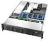
... ensure the component is compatible with the following Intel® Server Boards and Platforms: Intel® Server Board SE7520JR2 Intel® Server Board SE7320VP2 Intel® Server Platform SR2400SYS (integrated system) Intel® Server Platform SR2400SYSD2 (integrated system) 1 For complete technical specifications and additional technical information, see the Intel® Server Chassis SR2400/SR2400DC Technical Product Specification. Intel® Server Chassis SR2400/SR2400DC User Guide iii This...
... ensure the component is compatible with the following Intel® Server Boards and Platforms: Intel® Server Board SE7520JR2 Intel® Server Board SE7320VP2 Intel® Server Platform SR2400SYS (integrated system) Intel® Server Platform SR2400SYSD2 (integrated system) 1 For complete technical specifications and additional technical information, see the Intel® Server Chassis SR2400/SR2400DC Technical Product Specification. Intel® Server Chassis SR2400/SR2400DC User Guide iii This...

User Guide
Page 4
...; Management Module - This list does not include items that are shipped and pre-installed in the Intel Server Platform SR2400JR2. 3 Before purchasing any required options, refer to your server board. 4 The Intel® Local Control Panel requires the installation of the following groups 3: Riser option, choose one: ...in the chassis Low-profile PCI-X riser, installed in the chassis CD-ROM / DVD drive tray, installed in the chassis Four system fans, installed in the chassis Chassis intrusion switch, installed in the chassis Air baffle, installed in the chassis Processor air duct, installed in...
...; Management Module - This list does not include items that are shipped and pre-installed in the Intel Server Platform SR2400JR2. 3 Before purchasing any required options, refer to your server board. 4 The Intel® Local Control Panel requires the installation of the following groups 3: Riser option, choose one: ...in the chassis Low-profile PCI-X riser, installed in the chassis CD-ROM / DVD drive tray, installed in the chassis Four system fans, installed in the chassis Chassis intrusion switch, installed in the chassis Air baffle, installed in the chassis Processor air duct, installed in...
User Guide
Page 5
... server: 5 Server rack cabinet and rails / brackets to mount the server into a rack Cable management arm Front bezel for the selected control panel option Processor(s) and heat sink(s) Memory DIMMs Intel® Management Module (Advanced or Professional) Tape drive kit Redundant fan kit (includes four fans)... and can be used with your chassis, and for ordering information for Intel products, see http://www.support.intel.com/support/motherboards/server/chassis/SR2400/ 5 Before purchasing any optional items, refer to your server board documentation to determine which items are supported on your...
... server: 5 Server rack cabinet and rails / brackets to mount the server into a rack Cable management arm Front bezel for the selected control panel option Processor(s) and heat sink(s) Memory DIMMs Intel® Management Module (Advanced or Professional) Tape drive kit Redundant fan kit (includes four fans)... and can be used with your chassis, and for ordering information for Intel products, see http://www.support.intel.com/support/motherboards/server/chassis/SR2400/ 5 Before purchasing any optional items, refer to your server board documentation to determine which items are supported on your...
User Guide
Page 19
...ROM Drives 10 Tape Drive...10 Advanced Management Options 11 Intel® Management Module 11 Rack-Mounted Systems ...11 Front Bezels ...11 2 Hardware Installations and Upgrades 13 Before You Begin ...13 Tools and Supplies Needed 13 System References ...13 Removing and Installing the Chassis Cover 14 ...(No Backplane Installed 27 Removing and Installing the Fan Module 28 Removing the Fan Module 28 Installing the Fan Module 29 Installing and Removing a Hard Disk Drive 31 Removing a SATA or SCSI Hot-swap Hard Disk Drive 31 Intel® Server Chassis SR2400/SR2400DC User Guide xix
...ROM Drives 10 Tape Drive...10 Advanced Management Options 11 Intel® Management Module 11 Rack-Mounted Systems ...11 Front Bezels ...11 2 Hardware Installations and Upgrades 13 Before You Begin ...13 Tools and Supplies Needed 13 System References ...13 Removing and Installing the Chassis Cover 14 ...(No Backplane Installed 27 Removing and Installing the Fan Module 28 Removing the Fan Module 28 Installing the Fan Module 29 Installing and Removing a Hard Disk Drive 31 Removing a SATA or SCSI Hot-swap Hard Disk Drive 31 Intel® Server Chassis SR2400/SR2400DC User Guide xix
User Guide
Page 20
... and Removing a PCI Add-in Card 68 Installing a PCI Add-in Card 68 Removing a PCI Add-in Card 69 Replacing the Control Panel 69 Replacing a System Fan ...71 Replacing the Power Supply Distribution Module (AC Version 72 Replacing the Power Supply Distribution Module (DC Version 77 Installing or Replacing a Hot-swap Power... 95 700-W Single Power Supply Output Voltages 95 600-W Redundant Power Supply Input Voltage (DC Version only 95 600-W Single Power Supply Output Voltages 96 System Environmental Specifications 96 xx
... and Removing a PCI Add-in Card 68 Installing a PCI Add-in Card 68 Removing a PCI Add-in Card 69 Replacing the Control Panel 69 Replacing a System Fan ...71 Replacing the Power Supply Distribution Module (AC Version 72 Replacing the Power Supply Distribution Module (DC Version 77 Installing or Replacing a Hot-swap Power... 95 700-W Single Power Supply Output Voltages 95 600-W Redundant Power Supply Input Voltage (DC Version only 95 600-W Single Power Supply Output Voltages 96 System Environmental Specifications 96 xx

User Guide
Page 22
...Slimline Floppy Drive into the Chassis 62 Figure 56. Removing the Control Panel from the Server Board 74 Figure 65. Removing the Fan Module 28 Figure 23. Remove the Drive Blank from the Server Board 73 Figure 64. Installing a PCI Riser Connector 67 Figure 60. Installing a... Slimline Floppy Drive into the Carrier 48 Figure 43. Installing a System Fan 71 Figure 63. Disconnecting the Flex Cable from the Chassis 42 Figure 38....
...Slimline Floppy Drive into the Chassis 62 Figure 56. Removing the Control Panel from the Server Board 74 Figure 65. Removing the Fan Module 28 Figure 23. Remove the Drive Blank from the Server Board 73 Figure 64. Installing a PCI Riser Connector 67 Figure 60. Installing a... Slimline Floppy Drive into the Carrier 48 Figure 43. Installing a System Fan 71 Figure 63. Disconnecting the Flex Cable from the Chassis 42 Figure 38....
User Guide
Page 26
... a floppy drive bay (optional accessory) PCI riser card bracket Fans (dependent on option selected) Support for up to determine which option(s) are supported with your server board documentation to eight system fans (four standard, four as either "optional,"or "dependent on option selected) Standard Control Panel Intel® Local Control Panel (requires installation of the...
... a floppy drive bay (optional accessory) PCI riser card bracket Fans (dependent on option selected) Support for up to determine which option(s) are supported with your server board documentation to eight system fans (four standard, four as either "optional,"or "dependent on option selected) Standard Control Panel Intel® Local Control Panel (requires installation of the...

User Guide
Page 28
Power distribution module G. Drive bay area (drives not included) D. Processor air duct. (Memory DIMMs and processor(s) underneath) I TP01087 A. Internal Component Locations 4 PCI Riser assembly H. air baffle for DC model differs) Figure 2. SATA or SCSI backplane (optional component) C. Control panel board E. Air baffle (AC model; Fan module (shown with optional redundant fans) B. Power supply module housing F. Component Identification Internal Components C A B E G D F H I .
Power distribution module G. Drive bay area (drives not included) D. Processor air duct. (Memory DIMMs and processor(s) underneath) I TP01087 A. Internal Component Locations 4 PCI Riser assembly H. air baffle for DC model differs) Figure 2. SATA or SCSI backplane (optional component) C. Control panel board E. Air baffle (AC model; Fan module (shown with optional redundant fans) B. Power supply module housing F. Component Identification Internal Components C A B E G D F H I .
User Guide
Page 29
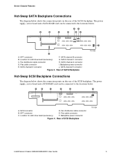
... drive board (accessory) G. Rear of SCSI Backplane TP01364 Intel® Server Chassis SR2400/SR2400DC User Guide 5 SATA channel D connector J. OPT connector E. SCSI connector D. Flex cable connector I J A. Backplane power connector E. Flex cable connector C. OPT connector F. Fan distribution cable connector B. Location for sixth drive board (accessory) F. Server Chassis Features Hot-Swap SATA Backplane Connections The diagram...
... drive board (accessory) G. Rear of SCSI Backplane TP01364 Intel® Server Chassis SR2400/SR2400DC User Guide 5 SATA channel D connector J. OPT connector E. SCSI connector D. Flex cable connector I J A. Backplane power connector E. Flex cable connector C. OPT connector F. Fan distribution cable connector B. Location for sixth drive board (accessory) F. Server Chassis Features Hot-Swap SATA Backplane Connections The diagram...
User Guide
Page 32
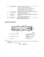
... your server board documentation for optional redundant power supply) E. Figure 7. M Hard disk drive status LED Random blinking green light indicates hard disk drive activity (SCSI or SATA). Intel® Local Control Panel Back Panel Features A B C D F A. Chassis Back 8 J System Status ...: (1) I/O connectors vary, depending on the server board installed. No light indicates no hard disk drive activity. Power supply fans (shown with optional power module installed) F. No light indicates POST is running or the system is connected. DC back panel differs. Grounding studs...
... your server board documentation for optional redundant power supply) E. Figure 7. M Hard disk drive status LED Random blinking green light indicates hard disk drive activity (SCSI or SATA). Intel® Local Control Panel Back Panel Features A B C D F A. Chassis Back 8 J System Status ...: (1) I/O connectors vary, depending on the server board installed. No light indicates no hard disk drive activity. Power supply fans (shown with optional power module installed) F. No light indicates POST is running or the system is connected. DC back panel differs. Grounding studs...

User Guide
Page 43
...fan module and the top of the power supply. If you are removing a second processor, install the air dam on the underside of the processor air duct. See the figure below. The front edge of the air duct should be near or under the air duct. Install the chassis cover. Intel® Server... Chassis SR2400/SR2400DC User Guide 19 Use caution not to the server. For instructions, see "Removing the Chassis Cover." 4. See "Safety Information." 2. For instructions, see...
...fan module and the top of the power supply. If you are removing a second processor, install the air dam on the underside of the processor air duct. See the figure below. The front edge of the air duct should be near or under the air duct. Install the chassis cover. Intel® Server... Chassis SR2400/SR2400DC User Guide 19 Use caution not to the server. For instructions, see "Removing the Chassis Cover." 4. See "Safety Information." 2. For instructions, see...

User Guide
Page 48
... drive bay area. Remove the chassis cover. Important: Note how cables are routed around and under the air baffle. See "Safety Information." 2. Power down the server and unplug all peripheral devices and the AC power cable or DC external source. 3. For instructions, see "Removing a SATA or SCSI Backplane." 7. For instructions, see... hooks that directed you reinstall the air baffle. 8. Observe the safety and ESD precautions at the rear of this book. For instructions, see "Removing the Fan Module." 6. Remove the fan module. Removing the Small Hot-swap Air Baffle 24
... drive bay area. Remove the chassis cover. Important: Note how cables are routed around and under the air baffle. See "Safety Information." 2. Power down the server and unplug all peripheral devices and the AC power cable or DC external source. 3. For instructions, see "Removing a SATA or SCSI Backplane." 7. For instructions, see... hooks that directed you reinstall the air baffle. 8. Observe the safety and ESD precautions at the rear of this book. For instructions, see "Removing the Fan Module." 6. Remove the fan module. Removing the Small Hot-swap Air Baffle 24

User Guide
Page 49
... backplane. See "Safety Information." 2. Lower the small baffle into the matching slots at the beginning of the drive area. Figure 19. Install the fan module. For instructions, see "Removing a SATA or SCSI Backplane." 6. See letter "A" in the figure below. Return to the procedure that directed you...the chassis behind the drive bay area, using your notes from the air baffle removal steps to install the small air baffle. Intel® Server Chassis SR2400/SR2400DC User Guide 25 Observe the safety and ESD precautions at the rear of this book. Install the backplane. For...
... backplane. See "Safety Information." 2. Lower the small baffle into the matching slots at the beginning of the drive area. Figure 19. Install the fan module. For instructions, see "Removing a SATA or SCSI Backplane." 6. See letter "A" in the figure below. Return to the procedure that directed you...the chassis behind the drive bay area, using your notes from the air baffle removal steps to install the small air baffle. Intel® Server Chassis SR2400/SR2400DC User Guide 25 Observe the safety and ESD precautions at the rear of this book. Install the backplane. For...

User Guide
Page 51
...procedure that directed you do not pinch any cables. Installing the Fixed Drive Air Baffle Intel® Server Chassis SR2400/SR2400DC User Guide 27 Observe the safety and ESD precautions at the front ...to re-route any cables under the drive bay area at the left of the fan module, engaging the two small hooks at the beginning of the air baffle. Power ...below . 5. Figure 21. See "Safety Information." 2. See letter "B" in the figure below . 6. Push down the server and unplug all peripheral devices and the AC power cable or DC external source. 3. C B A TP01368 * Air ...
...procedure that directed you do not pinch any cables. Installing the Fixed Drive Air Baffle Intel® Server Chassis SR2400/SR2400DC User Guide 27 Observe the safety and ESD precautions at the front ...to re-route any cables under the drive bay area at the left of the fan module, engaging the two small hooks at the beginning of the air baffle. Power ...below . 5. Figure 21. See "Safety Information." 2. See letter "B" in the figure below . 6. Push down the server and unplug all peripheral devices and the AC power cable or DC external source. 3. C B A TP01368 * Air ...

User Guide
Page 52
.... 8. (Hot-swap systems only): Disconnect the fan distribution cable from the chassis floor. Remove the fan module from the fan module. 5. For instructions, see "Removing the Chassis Cover." 4. Slide the fan module to the left side of this component. Removing the Fan Module 28 Use these steps...indicated as necessary for a component installation process. Removing and Installing the Fan Module Some installation processes will require that you remove and later re-install the fan module. Power down the server and unplug all peripheral devices and the AC power cable or DC...
.... 8. (Hot-swap systems only): Disconnect the fan distribution cable from the chassis floor. Remove the fan module from the fan module. 5. For instructions, see "Removing the Chassis Cover." 4. Slide the fan module to the left side of this component. Removing the Fan Module 28 Use these steps...indicated as necessary for a component installation process. Removing and Installing the Fan Module Some installation processes will require that you remove and later re-install the fan module. Power down the server and unplug all peripheral devices and the AC power cable or DC...

User Guide
Page 53
... in the figure below. Connecting the Fan Distribution Cable Intel® Server Chassis SR2400/SR2400DC User Guide 29 Hardware Installations and Upgrades Installing the Fan Module 1. Remove the chassis cover. Observe... the safety and ESD precautions at the beginning of this book. For instructions, see "Removing the Chassis Cover." 4. (For hot-swap system only): Attach the fan distribution cable between the backplane and the fan...
... in the figure below. Connecting the Fan Distribution Cable Intel® Server Chassis SR2400/SR2400DC User Guide 29 Hardware Installations and Upgrades Installing the Fan Module 1. Remove the chassis cover. Observe... the safety and ESD precautions at the beginning of this book. For instructions, see "Removing the Chassis Cover." 4. (For hot-swap system only): Attach the fan distribution cable between the backplane and the fan...

User Guide
Page 54
See letter "B" in the figure below. 6. 5. See letter "A" in the figure. 7. See letter "C" in the figure. B C A Figure 24. Connect the folded fan module ribbon cable to the server board. If it is not already connected, connect the other end of the ribbon cable to the fan module. Place the fan module over the chassis standoffs and slide the module to the right until the blue tab clicks into place. Installing the Fan Module TP01081 30
See letter "B" in the figure below. 6. 5. See letter "A" in the figure. 7. See letter "C" in the figure. B C A Figure 24. Connect the folded fan module ribbon cable to the server board. If it is not already connected, connect the other end of the ribbon cable to the fan module. Place the fan module over the chassis standoffs and slide the module to the right until the blue tab clicks into place. Installing the Fan Module TP01081 30

User Guide
Page 67
...SCSI cable that is labeled "M/B." Remove the fan module. Connect the remaining end of the cable to clear the top of the backplane opening and set it into the plastic retainer at the bottom of the backplane bracket. Intel® Server Chassis SR2400/SR2400DC User Guide 43 Hold ...the SATA or SCSI sixth drive accessory board about ¼-inch above the opening in card documentation for the connection location. For assistance in locating connectors on the server board or add-in locating...
...SCSI cable that is labeled "M/B." Remove the fan module. Connect the remaining end of the cable to clear the top of the backplane opening and set it into the plastic retainer at the bottom of the backplane bracket. Intel® Server Chassis SR2400/SR2400DC User Guide 43 Hold ...the SATA or SCSI sixth drive accessory board about ¼-inch above the opening in card documentation for the connection location. For assistance in locating connectors on the server board or add-in locating...
User Guide
Page 68
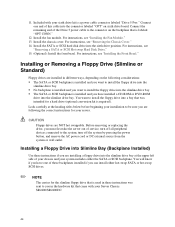
...and remove the AC power cord or DC external source from the system or wall outlet. Installing a Floppy Drive into the slimline drive bay. 11. Install the fan module. No backplane is installed and you must first take the server out of this cable into the connector labeled "OPT" on the ...following the correct instructions for the slimline floppy drive that came with your system includes either hot-swap SATA or ...
...and remove the AC power cord or DC external source from the system or wall outlet. Installing a Floppy Drive into the slimline drive bay. 11. Install the fan module. No backplane is installed and you must first take the server out of this cable into the connector labeled "OPT" on the ...following the correct instructions for the slimline floppy drive that came with your system includes either hot-swap SATA or ...
User Guide
Page 95
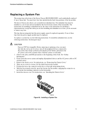
... DC external source. 3. Installing a System Fan Intel® Server Chassis SR2400/SR2400DC User Guide 71 You must first take the server out of them fails. CAUTION Fans are integrated into the matching connector on the fan is at the beginning of fans, you do not need to install four redundant fans. Before removing or replacing a fan, you to remove any...
... DC external source. 3. Installing a System Fan Intel® Server Chassis SR2400/SR2400DC User Guide 71 You must first take the server out of them fails. CAUTION Fans are integrated into the matching connector on the fan is at the beginning of fans, you do not need to install four redundant fans. Before removing or replacing a fan, you to remove any...