
User Guide
Page 3
... compatible with the following Intel® Server Boards and Platforms: Intel® Server Board SE7520JR2 Intel® Server Board SE7320VP2 Intel® Server Platform SR2400SYS (integrated system) Intel® Server Platform SR2400SYSD2 (integrated system) 1 For complete technical specifications and additional technical information, see the Intel® Server Chassis SR2400/SR2400DC Technical Product Specification. This manual is compatible with your server board. Intel® Server Chassis SR2400/SR2400DC User Guide iii...
... compatible with the following Intel® Server Boards and Platforms: Intel® Server Board SE7520JR2 Intel® Server Board SE7320VP2 Intel® Server Platform SR2400SYS (integrated system) Intel® Server Platform SR2400SYSD2 (integrated system) 1 For complete technical specifications and additional technical information, see the Intel® Server Chassis SR2400/SR2400DC Technical Product Specification. This manual is compatible with your server board. Intel® Server Chassis SR2400/SR2400DC User Guide iii...

User Guide
Page 4
... are supported on your server board documentation to below as the "hardware box" One 700-W power supply (AC version) or one 600-W power supply (DC version), installed in the chassis Low-profile PCI-X riser, installed in the chassis CD-ROM / DVD drive tray, installed in the chassis Four system fans, installed in... hot-swap backplane kit ⎯ SATA hot-swap backplane kit ⎯ Fixed SATA drive kit Control panel, choose one item from each of the optional Intel® Management Module - Your Server Chassis SR2400/SR2400DC shipped with the Intel Server Chassis SR2400/SR2400DC.
... are supported on your server board documentation to below as the "hardware box" One 700-W power supply (AC version) or one 600-W power supply (DC version), installed in the chassis Low-profile PCI-X riser, installed in the chassis CD-ROM / DVD drive tray, installed in the chassis Four system fans, installed in... hot-swap backplane kit ⎯ SATA hot-swap backplane kit ⎯ Fixed SATA drive kit Control panel, choose one item from each of the optional Intel® Management Module - Your Server Chassis SR2400/SR2400DC shipped with the Intel Server Chassis SR2400/SR2400DC.
User Guide
Page 5
... bay For information about which of these items have been tested and can be used with your chassis, and for ordering information for Intel products, see http://www.support.intel.com/support/motherboards/server/chassis/SR2400/ 5 Before purchasing any optional items, refer to your server board documentation to determine which items are supported on your...
... bay For information about which of these items have been tested and can be used with your chassis, and for ordering information for Intel products, see http://www.support.intel.com/support/motherboards/server/chassis/SR2400/ 5 Before purchasing any optional items, refer to your server board documentation to determine which items are supported on your...

User Guide
Page 6
...depth technical information about the accessories that have been tested with this server board, use the following resources. These sources are available at http://support.intel.com/support/motherboards/server/chassis/SR2400/ Unless otherwise indicated in the table below, once on this Web ...of the screen Accessories or other Intel server products Search for "Spares and Configuration Guide" Hardware (peripheral boards, adapter cards) and operating systems that have been tested with this product Search for "Tested Hardware and Operating System List" Server boards that have been tested ...
...depth technical information about the accessories that have been tested with this server board, use the following resources. These sources are available at http://support.intel.com/support/motherboards/server/chassis/SR2400/ Unless otherwise indicated in the table below, once on this Web ...of the screen Accessories or other Intel server products Search for "Spares and Configuration Guide" Hardware (peripheral boards, adapter cards) and operating systems that have been tested with this product Search for "Tested Hardware and Operating System List" Server boards that have been tested ...

User Guide
Page 7
..., schools, computer rooms, and similar commercial type locations. The nuts on the chassis earth-ground studs should be a minimum 18AWG connected to the server. Intel® Server Chassis SR2400/SR2400DC User Guide vii See "Regulatory and Integration Information" for the system. The main disconnect must be readily accessible, and it must be connected to the...
..., schools, computer rooms, and similar commercial type locations. The nuts on the chassis earth-ground studs should be a minimum 18AWG connected to the server. Intel® Server Chassis SR2400/SR2400DC User Guide vii See "Regulatory and Integration Information" for the system. The main disconnect must be readily accessible, and it must be connected to the...

User Guide
Page 9
... surface-when handling components. 6. Refer servicing only to the main (AC) power. Turn off the system by wearing an antistatic wrist strap attached to access the inside of the system if a padlock has been installed. 2. Intel® Server Chassis SR2400/SR2400DC User Guide ix The power cord(s) is not the exact type required. SAFETY STEPS...
... surface-when handling components. 6. Refer servicing only to the main (AC) power. Turn off the system by wearing an antistatic wrist strap attached to access the inside of the system if a padlock has been installed. 2. Intel® Server Chassis SR2400/SR2400DC User Guide ix The power cord(s) is not the exact type required. SAFETY STEPS...
User Guide
Page 19
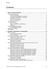
... / CD-ROM / DVD-ROM Drives 10 Tape Drive...10 Advanced Management Options 11 Intel® Management Module 11 Rack-Mounted Systems ...11 Front Bezels ...11 2 Hardware Installations and Upgrades 13 Before You Begin ...13 Tools and Supplies Needed 13 System References ...13 Removing and Installing the Chassis Cover 14 Removing the Chassis Cover... Fan Module 28 Installing the Fan Module 29 Installing and Removing a Hard Disk Drive 31 Removing a SATA or SCSI Hot-swap Hard Disk Drive 31 Intel® Server Chassis SR2400/SR2400DC User Guide xix
... / CD-ROM / DVD-ROM Drives 10 Tape Drive...10 Advanced Management Options 11 Intel® Management Module 11 Rack-Mounted Systems ...11 Front Bezels ...11 2 Hardware Installations and Upgrades 13 Before You Begin ...13 Tools and Supplies Needed 13 System References ...13 Removing and Installing the Chassis Cover 14 Removing the Chassis Cover... Fan Module 28 Installing the Fan Module 29 Installing and Removing a Hard Disk Drive 31 Removing a SATA or SCSI Hot-swap Hard Disk Drive 31 Intel® Server Chassis SR2400/SR2400DC User Guide xix

User Guide
Page 21
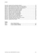
... 114 How to Obtain Warranty Service 115 Telephone Support...115 Returning a Defective Product 115 Figures Figure 1. Removing the Processor Air Duct 18 Figure 14. Intel® Server Chassis SR2400/SR2400DC 1 Figure 2. Optional Peripherals ...9 Figure 9. Installing the Processor Air Duct 19 Figure 15. Rear of SATA Backplane 5 Figure 4. Removing the Front Bezel 16 Figure...
... 114 How to Obtain Warranty Service 115 Telephone Support...115 Returning a Defective Product 115 Figures Figure 1. Removing the Processor Air Duct 18 Figure 14. Intel® Server Chassis SR2400/SR2400DC 1 Figure 2. Optional Peripherals ...9 Figure 9. Installing the Processor Air Duct 19 Figure 15. Rear of SATA Backplane 5 Figure 4. Removing the Front Bezel 16 Figure...
User Guide
Page 23
... Figure 81. Connecting the Tape Drive Cables 92 Figure 84. Table 2. Removing a SATA or SCSI Backplane 87 Figure 78. Server Chassis Features 2 Product Certification Markings 102 Product Certification Markings 103 Intel® Server Chassis SR2400/SR2400DC User Guide xxiii Inserting the Tape Drive Carrier into the Carrier 91 Figure 82. Removing the Power Distribution...
... Figure 81. Connecting the Tape Drive Cables 92 Figure 84. Table 2. Removing a SATA or SCSI Backplane 87 Figure 78. Server Chassis Features 2 Product Certification Markings 102 Product Certification Markings 103 Intel® Server Chassis SR2400/SR2400DC User Guide xxiii Inserting the Tape Drive Carrier into the Carrier 91 Figure 82. Removing the Power Distribution...

User Guide
Page 25
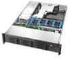
Server Chassis Features 1 Server Chassis Features This chapter briefly describes the main features of important components and connections on the server chassis. The Intel® Server Chassis SR2400/SR2400DC is shown in the following picture. This chapter provides pictures of the product, a list of the server features, and diagrams showing the location of Intel® Server Chassis SR2400/SR2400DC. Figure 1. Intel® Server Chassis SR2400/SR2400DC Intel® Server Chassis SR2400/SR2400DC User Guide 1
Server Chassis Features 1 Server Chassis Features This chapter briefly describes the main features of important components and connections on the server chassis. The Intel® Server Chassis SR2400/SR2400DC is shown in the following picture. This chapter provides pictures of the product, a list of the server features, and diagrams showing the location of Intel® Server Chassis SR2400/SR2400DC. Figure 1. Intel® Server Chassis SR2400/SR2400DC Intel® Server Chassis SR2400/SR2400DC User Guide 1
User Guide
Page 27
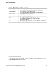
... 600-W power supply (optional accessory) System Security Lockable front bezel (optional accessory) Chassis intrusion switch Lock attach point for chassis cover USB One front panel USB port with Standard Control Panel Two front panel USB ports with Intel® Local Control Panel Two back ... Standard Control Panel)7 One rear panel video port 7 Video connections must be used separately. The server board and chassis do not support synchronous use of video out of the front and back of the chassis. Server Chassis Features Table 1. Intel® Server Chassis SR2400/SR2400DC User Guide 3
... 600-W power supply (optional accessory) System Security Lockable front bezel (optional accessory) Chassis intrusion switch Lock attach point for chassis cover USB One front panel USB port with Standard Control Panel Two front panel USB ports with Intel® Local Control Panel Two back ... Standard Control Panel)7 One rear panel video port 7 Video connections must be used separately. The server board and chassis do not support synchronous use of video out of the front and back of the chassis. Server Chassis Features Table 1. Intel® Server Chassis SR2400/SR2400DC User Guide 3
User Guide
Page 29
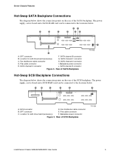
... J. Rear of SATA Backplane TP01363 Hot-Swap SCSI Backplane Connections The diagram below shows the connection points on the rear of SCSI Backplane TP01364 Intel® Server Chassis SR2400/SR2400DC User Guide 5 Flex cable connector C. Location for sixth drive board (accessory) G. Fan distribution cable connector H. Backplane power connector E. Fan distribution cable connector B. OPT...
... J. Rear of SATA Backplane TP01363 Hot-Swap SCSI Backplane Connections The diagram below shows the connection points on the rear of SCSI Backplane TP01364 Intel® Server Chassis SR2400/SR2400DC User Guide 5 Flex cable connector C. Location for sixth drive board (accessory) G. Fan distribution cable connector H. Backplane power connector E. Fan distribution cable connector B. OPT...
User Guide
Page 31
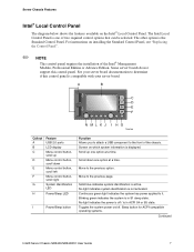
... state. Sleep button for ACPI-compatible operating systems. Continued Intel® Server Chassis SR2400/SR2400DC User Guide 7 Move to it. Server Chassis Features Intel® Local Control Panel The diagram below shows the features available on which system information is displayed. The Intel Local Control Panel is active. See your server board documentation to determine if this control panel...
... state. Sleep button for ACPI-compatible operating systems. Continued Intel® Server Chassis SR2400/SR2400DC User Guide 7 Move to it. Server Chassis Features Intel® Local Control Panel The diagram below shows the features available on which system information is displayed. The Intel Local Control Panel is active. See your server board documentation to determine if this control panel...
User Guide
Page 33
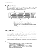
...slimline bay) can consume up to 17 watts of power each. Drives must be specified to the system, turn off all SCSI or Serial ATA hard drives. The Intel Server Chassis SR2400/SR2400DC does not support all peripheral devices connected to run at a maximum ambient temperature of five,... NOTES Drives can be converted to a list of service, turn off the system by pressing the power button, and unplug the AC power cord or DC external source from the system or wall outlet. Intel® Server Chassis SR2400/SR2400DC User Guide 9 C. To use the bay for installing a tape drive...
...slimline bay) can consume up to 17 watts of power each. Drives must be specified to the system, turn off all SCSI or Serial ATA hard drives. The Intel Server Chassis SR2400/SR2400DC does not support all peripheral devices connected to run at a maximum ambient temperature of five,... NOTES Drives can be converted to a list of service, turn off the system by pressing the power button, and unplug the AC power cord or DC external source from the system or wall outlet. Intel® Server Chassis SR2400/SR2400DC User Guide 9 C. To use the bay for installing a tape drive...

User Guide
Page 34
...Floppy / CD-ROM / DVD-ROM Drives The slimline drive carriers included with your server chassis can be inserted or removed only when system power is for a CD-ROM or DVD ROM; The Intel Server Chassis SR2400 does not support all slimline floppy, CDROM or DVD-ROM hard drives. See "... CD-ROM / DVD-ROM cage can be used with the chassis. For installation instructions for a floppy drive, see "Installing a Tape Drive." 10 Intel provides accessory kits for an Internet link to accommodate the height of a tape drive. For instructions on installing a tape drive, see "Installing or Removing...
...Floppy / CD-ROM / DVD-ROM Drives The slimline drive carriers included with your server chassis can be inserted or removed only when system power is for a CD-ROM or DVD ROM; The Intel Server Chassis SR2400 does not support all slimline floppy, CDROM or DVD-ROM hard drives. See "... CD-ROM / DVD-ROM cage can be used with the chassis. For installation instructions for a floppy drive, see "Installing a Tape Drive." 10 Intel provides accessory kits for an Internet link to accommodate the height of a tape drive. For instructions on installing a tape drive, see "Installing or Removing...
User Guide
Page 35
...instructions provided with the Intel® Local Control Panel: ADRLCDBEZEL Intel® Server Chassis SR2400/SR2400DC User Guide 11 Advanced Edition includes a hardware mezzanine card, 10/100 Mb NIC mezzanine card, and cables. The Intel SR2400 server chassis can be mounted into the server board. Each bezel ... the rack, the second system in the rail kit. The Intel Management Module - The other words, install the first system in the rack into a rack, Intel recommends you install systems from the bottom, and so on installing either Intel Management Module, see "Removing...
...instructions provided with the Intel® Local Control Panel: ADRLCDBEZEL Intel® Server Chassis SR2400/SR2400DC User Guide 11 Advanced Edition includes a hardware mezzanine card, 10/100 Mb NIC mezzanine card, and cables. The Intel SR2400 server chassis can be mounted into the server board. Each bezel ... the rack, the second system in the rail kit. The Intel Management Module - The other words, install the first system in the rack into a rack, Intel recommends you install systems from the bottom, and so on installing either Intel Management Module, see "Removing...

User Guide
Page 37
...) Antistatic wrist strap and conductive foam pad (recommended) System References All references to the safety instructions at the beginning of the chassis as the processor and memory DIMMs, see the instructions provided with your server product, pay close attention to left, right, front,...and are based on the reader facing the front of this manual. This document provides instructions for normal operation. Intel® Server Chassis SR2400/SR2400DC User Guide 13 See "Safety Information." Hardware Installations and Upgrades 2 Hardware Installations and Upgrades Before You Begin ...
...) Antistatic wrist strap and conductive foam pad (recommended) System References All references to the safety instructions at the beginning of the chassis as the processor and memory DIMMs, see the instructions provided with your server product, pay close attention to left, right, front,...and are based on the reader facing the front of this manual. This document provides instructions for normal operation. Intel® Server Chassis SR2400/SR2400DC User Guide 13 See "Safety Information." Hardware Installations and Upgrades 2 Hardware Installations and Upgrades Before You Begin ...

User Guide
Page 38
...Remove the shipping screw (if installed). Removing the Chassis Cover 14 Before removing the top cover, power down the server and unplug all peripheral devices connected to the server. See "Safety Information." 2. Turn off all peripheral devices and the AC power cable or DC external source. Disconnect... help lift it upward to remove it (see letter "C"). 6. Removing and Installing the Chassis Cover Removing the Chassis Cover The Intel® Server Chassis SR2400/SR2400DC must be needed to prevent the chassis from sliding on your work surface. 1. Observe the safety and ESD precautions at ...
...Remove the shipping screw (if installed). Removing the Chassis Cover 14 Before removing the top cover, power down the server and unplug all peripheral devices connected to the server. See "Safety Information." 2. Turn off all peripheral devices and the AC power cable or DC external source. Disconnect... help lift it upward to remove it (see letter "C"). 6. Removing and Installing the Chassis Cover Removing the Chassis Cover The Intel® Server Chassis SR2400/SR2400DC must be needed to prevent the chassis from sliding on your work surface. 1. Observe the safety and ESD precautions at ...

User Guide
Page 39
See letter "A" in the figure. 4. See letter "B" in the figure below. 3. (Optional): Insert the shipping screw at the center of the cover sit just inside the chassis sidewalls. 2. Installing the Chassis Cover Intel® Server Chassis SR2400/SR2400DC User Guide 15 Reconnect all peripheral devices and the AC power cord or DC external source. Hardware Installations and Upgrades Installing the Chassis Cover 1. Place the cover over the chassis so that the side edges of the top cover. A B Figure 10. Slide the cover forward until it clicks into place.
See letter "A" in the figure. 4. See letter "B" in the figure below. 3. (Optional): Insert the shipping screw at the center of the cover sit just inside the chassis sidewalls. 2. Installing the Chassis Cover Intel® Server Chassis SR2400/SR2400DC User Guide 15 Reconnect all peripheral devices and the AC power cord or DC external source. Hardware Installations and Upgrades Installing the Chassis Cover 1. Place the cover over the chassis so that the side edges of the top cover. A B Figure 10. Slide the cover forward until it clicks into place.

User Guide
Page 40
...accessories for the Standard Control Panel and the other is used with the control panel area at the top right. One is used for the Server Chassis SR2400. Disconnect any cables attached to the front of the control panel. 3. Removing the Front Bezel Use the steps below if your chassis, make... sure you are installing a bezel on your system includes either the standard front bezel or the front bezel for both bezels. Figure 11. If you position it with the Intel® Local Control Panel. Removing the Front Bezel TP01344 16 Pull the bezel out...
...accessories for the Standard Control Panel and the other is used with the control panel area at the top right. One is used for the Server Chassis SR2400. Disconnect any cables attached to the front of the control panel. 3. Removing the Front Bezel Use the steps below if your chassis, make... sure you are installing a bezel on your system includes either the standard front bezel or the front bezel for both bezels. Figure 11. If you position it with the Intel® Local Control Panel. Removing the Front Bezel TP01344 16 Pull the bezel out...

