
Product Specification
Page 4
...-System ...- 20 - 2.1 System Fans...- 21 - 2.2 Power Supply Fans 22 - 2.3 CPU/Memory Air Duct and Side Air Baffle 22 - 2.4 Hard Drive Bays 23 - 3. Table of Contents 1. Intel® Server Chassis SC1400UP Feature Summary 13 - 1.1 Chassis Views 13 - 1.2 Chassis Dimensions 13 - 1.3 Intel® Server Chassis SC1400UP System Components 14 - 1.4 Rear Panel Components 15 - 1.5 Hard Drive and Peripheral...
...-System ...- 20 - 2.1 System Fans...- 21 - 2.2 Power Supply Fans 22 - 2.3 CPU/Memory Air Duct and Side Air Baffle 22 - 2.4 Hard Drive Bays 23 - 3. Table of Contents 1. Intel® Server Chassis SC1400UP Feature Summary 13 - 1.1 Chassis Views 13 - 1.2 Chassis Dimensions 13 - 1.3 Intel® Server Chassis SC1400UP System Components 14 - 1.4 Rear Panel Components 15 - 1.5 Hard Drive and Peripheral...

Product Specification
Page 9
... Height PCI-Express Riser Card Mechanical Drawing 49 Figure 34. Intel® Server Chassis SC1400UP Peripheral Bay Configuration Options 24 Figure 15. Airflow Characteristics 51 - Revision 1.0 ix Major Chassis Components 14 Figure 3. Control Panel Module 16 Figure 6. Optional Front Bezel 18 Figure 8. Intel® Server Platform SE7221BK1-E System Fan headers 4, 5, 6, 7, 8 21 Figure 12. Drive Tray with...
... Height PCI-Express Riser Card Mechanical Drawing 49 Figure 34. Intel® Server Chassis SC1400UP Peripheral Bay Configuration Options 24 Figure 15. Airflow Characteristics 51 - Revision 1.0 ix Major Chassis Components 14 Figure 3. Control Panel Module 16 Figure 6. Optional Front Bezel 18 Figure 8. Intel® Server Platform SE7221BK1-E System Fan headers 4, 5, 6, 7, 8 21 Figure 12. Drive Tray with...

Product Specification
Page 14
Intel® Server Chassis SC1400UP / Intel® Server Platform SR1425BK1-E 1.3 Intel® Server Chassis SC1400UP System Components A Power supply B Chassis Intrusion Switch C Full length PCI Add in card slot D PCI Riser Card Assembly Placement E System Fan Module F CPU Air Duct Placement G Control Panel H Hard Drive Bays I Chassis Handle J Slim Line Drive Bay K PS / Electronics Bay Isolation Air Baffle L Power Supply Fans Figure 2. Major Chassis Components Revision 1.0 - 14 -
Intel® Server Chassis SC1400UP / Intel® Server Platform SR1425BK1-E 1.3 Intel® Server Chassis SC1400UP System Components A Power supply B Chassis Intrusion Switch C Full length PCI Add in card slot D PCI Riser Card Assembly Placement E System Fan Module F CPU Air Duct Placement G Control Panel H Hard Drive Bays I Chassis Handle J Slim Line Drive Bay K PS / Electronics Bay Isolation Air Baffle L Power Supply Fans Figure 2. Major Chassis Components Revision 1.0 - 14 -

Product Specification
Page 15
...backplane. If both a CDROM or DVD/CDR and Floppy drive are required, on the server board. The slim-line peripheral bay is available to convert the first 1" hard drive bay to a floppy drive bay. A PS2 keyboard connector B PS2 mouse connector C Serial port A connector (DB9) ... Feature Overview 1.5 Hard Drive and Peripheral Bays The Server Chassis SC1400UP is designed to support up to support several different hard drive and peripheral configurations. Revision 1.0 - 15 - Intel® Server Chassis SC1400UP / Intel® Server Platform SR1425BK1-E 1.4 Rear Panel Components On the back...
...backplane. If both a CDROM or DVD/CDR and Floppy drive are required, on the server board. The slim-line peripheral bay is available to convert the first 1" hard drive bay to a floppy drive bay. A PS2 keyboard connector B PS2 mouse connector C Serial port A connector (DB9) ... Feature Overview 1.5 Hard Drive and Peripheral Bays The Server Chassis SC1400UP is designed to support up to support several different hard drive and peripheral configurations. Revision 1.0 - 15 - Intel® Server Chassis SC1400UP / Intel® Server Platform SR1425BK1-E 1.4 Rear Panel Components On the back...

Product Specification
Page 16
Intel® Server Chassis SC1400UP / Intel® Server Platform SR1425BK1-E Figure 4. The entire module assembly slides into a predefined slot in design. Front Panel Feature Overview A Slim-line drive bay (CDROM or DVD/CDR or Floppy) B Control Panel C Hard Drive Fault/Activity LED D 1" Hard Drive Bays E Chassis Handle 1.6 Control Panel The Server Chassis SC1400UP control panel assembly is pre-assembled and modular in the front of the chassis. Revision 1.0 Figure 5. Control Panel Module - 16 -
Intel® Server Chassis SC1400UP / Intel® Server Platform SR1425BK1-E Figure 4. The entire module assembly slides into a predefined slot in design. Front Panel Feature Overview A Slim-line drive bay (CDROM or DVD/CDR or Floppy) B Control Panel C Hard Drive Fault/Activity LED D 1" Hard Drive Bays E Chassis Handle 1.6 Control Panel The Server Chassis SC1400UP control panel assembly is pre-assembled and modular in the front of the chassis. Revision 1.0 Figure 5. Control Panel Module - 16 -

Product Specification
Page 20
...dual rotor fans, one 40x40x28mm single rotor fan, two 40x40x28mm power supply fans, CPU/Memory air duct, and PS/Electronics Bay Isolation Air Baffle, to provide the necessary cooling and airflow to the system. A fan on the SC1400UP is not necessary... fail, the system should be brought down as soon as possible to be properly installed. Intel® Server Chassis SC1400UP Cooling Subsystem A System Fan #4 D Air Baffle B Fans 5, 6, 7, 8 E CPU Heat Sink C CPU / Memory Air Duct Revision 1.0 - 20 - Intel® Server Chassis SC1400UP / Intel® Server Platform SR1425BK1-E 2.
...dual rotor fans, one 40x40x28mm single rotor fan, two 40x40x28mm power supply fans, CPU/Memory air duct, and PS/Electronics Bay Isolation Air Baffle, to provide the necessary cooling and airflow to the system. A fan on the SC1400UP is not necessary... fail, the system should be brought down as soon as possible to be properly installed. Intel® Server Chassis SC1400UP Cooling Subsystem A System Fan #4 D Air Baffle B Fans 5, 6, 7, 8 E CPU Heat Sink C CPU / Memory Air Duct Revision 1.0 - 20 - Intel® Server Chassis SC1400UP / Intel® Server Platform SR1425BK1-E 2.

Product Specification
Page 22
... into three stand-offs with one end fitting under the back edge of the hard drive bay Figure 12. The system fans are responsible for the cooling of the power supply and drive bay 1 (the far left hard drive as possible to the baseboard system fan header #4 (JP5J2...as soon as viewed from that connects directly to have the fan replaced. The CPU air duct is no fan redundancy. Intel® Server Chassis SC1400UP / Intel® Server Platform SR1425BK1-E The following table provides the pin-outs for all the fans within the module is mounted into the thermal sensor data record...
... into three stand-offs with one end fitting under the back edge of the hard drive bay Figure 12. The system fans are responsible for the cooling of the power supply and drive bay 1 (the far left hard drive as possible to the baseboard system fan header #4 (JP5J2...as soon as viewed from that connects directly to have the fan replaced. The CPU air duct is no fan redundancy. Intel® Server Chassis SC1400UP / Intel® Server Platform SR1425BK1-E The following table provides the pin-outs for all the fans within the module is mounted into the thermal sensor data record...

Product Specification
Page 23
...installed if the air damn is removed, the system will not meet the thermal cooling requirements of the system. Intel® Server Chassis SC1400UP / Intel® Server Platform SR1425BK1-E designed to maintain system thermals. Note: Once the air damn is removed from the CPU air duct, it... cannot be reinstalled. 2.4 Hard Drive Bays Hard drive bays must ether have a hard drive or drive blank installed in degraded performance...
...installed if the air damn is removed, the system will not meet the thermal cooling requirements of the system. Intel® Server Chassis SC1400UP / Intel® Server Platform SR1425BK1-E designed to maintain system thermals. Note: Once the air damn is removed from the CPU air duct, it... cannot be reinstalled. 2.4 Hard Drive Bays Hard drive bays must ether have a hard drive or drive blank installed in degraded performance...

Product Specification
Page 24
... whether a SATA or SCSI backplane is cabled to the Intel Server Chassis SC1400UP and Intel Server Board SE7221BK1-E. The interposer card has three connectors; Intel® Server Chassis SC1400UP / Intel® Server Platform SR1425BK1-E 3. Peripheral and Hard Drive Support The server chassis SC1400UP provides three hard drive bays and one slim-line peripheral drive bay at the front of a backplane. View of Slim...
... whether a SATA or SCSI backplane is cabled to the Intel Server Chassis SC1400UP and Intel Server Board SE7221BK1-E. The interposer card has three connectors; Intel® Server Chassis SC1400UP / Intel® Server Platform SR1425BK1-E 3. Peripheral and Hard Drive Support The server chassis SC1400UP provides three hard drive bays and one slim-line peripheral drive bay at the front of a backplane. View of Slim...

Product Specification
Page 25
... kit which comes with the SC1400UP chassis. Optional Floppy Drive Configuration Revision 1.0 - 25 - Figure 16. Intel® Server Chassis SC1400UP / Intel® Server Platform SR1425BK1-E Table 3. 4-pin floppy power connector Pinout (J3) Pin Name 1 P12V 2 GND 3 GND 4 P5V... The power cable for the floppy drive is cabled to install a floppy drive into the hard drive bay directly beneath the slim-line drive bay...
... kit which comes with the SC1400UP chassis. Optional Floppy Drive Configuration Revision 1.0 - 25 - Figure 16. Intel® Server Chassis SC1400UP / Intel® Server Platform SR1425BK1-E Table 3. 4-pin floppy power connector Pinout (J3) Pin Name 1 P12V 2 GND 3 GND 4 P5V... The power cable for the floppy drive is cabled to install a floppy drive into the hard drive bay directly beneath the slim-line drive bay...

Product Specification
Page 26
The interposer card has three connectors; The power cable for the drive is included in the SC1400UP in the hard drive bay. Intel® Server Chassis SC1400UP / Intel® Server Platform SR1425BK1-E 3.1.1.2 CDROM or DVD-CDR Drive Use with or without Backplane present Regardless of whether a backplane is present or not, the slim-line CDROM or DVD-...
The interposer card has three connectors; The power cable for the drive is included in the SC1400UP in the hard drive bay. Intel® Server Chassis SC1400UP / Intel® Server Platform SR1425BK1-E 3.1.1.2 CDROM or DVD-CDR Drive Use with or without Backplane present Regardless of whether a backplane is present or not, the slim-line CDROM or DVD-...

Product Specification
Page 27
... 29 30 GND 31 32 NC_IDEIO16_L 33 34 IDE_CBL_DET_S 35 36 IDE_SDA 37 38 IDE_SDCS1_L 39 40 GND 3.2 Hard Disk Drive Bays The server chassis SC1400UP can be populated to or extraction from inside the chassis. For cabled drive configurations, the SATA drives are mounted ...hot swap SCSI or SATA hard disk drives or fixed SATA drive configurations. Note: All hard drive bays must be configured to the legacy IDE connector on the baseboard. Intel® Server Chassis SC1400UP / Intel® Server Platform SR1425BK1-E The third connector has 40 pins and is only removable from the drive...
... 29 30 GND 31 32 NC_IDEIO16_L 33 34 IDE_CBL_DET_S 35 36 IDE_SDA 37 38 IDE_SDCS1_L 39 40 GND 3.2 Hard Disk Drive Bays The server chassis SC1400UP can be populated to or extraction from inside the chassis. For cabled drive configurations, the SATA drives are mounted ...hot swap SCSI or SATA hard disk drives or fixed SATA drive configurations. Note: All hard drive bays must be configured to the legacy IDE connector on the baseboard. Intel® Server Chassis SC1400UP / Intel® Server Platform SR1425BK1-E The third connector has 40 pins and is only removable from the drive...

Product Specification
Page 28
... Drive Connector 3.2.2 Fixed Drive Trays In a fixed drive configuration, each hard drive must be mounted to slide into the drive bay and lock into place. Revision 1.0 - 28 - Intel® Server Chassis SC1400UP / Intel® Server Platform SR1425BK1-E 3.2.1 Hot Swap Hard Disk Drive Trays In a hot swap configuration, each SATA/SCSI hard drive must be mounted to be...
... Drive Connector 3.2.2 Fixed Drive Trays In a fixed drive configuration, each hard drive must be mounted to slide into the drive bay and lock into place. Revision 1.0 - 28 - Intel® Server Chassis SC1400UP / Intel® Server Platform SR1425BK1-E 3.2.1 Hot Swap Hard Disk Drive Trays In a hot swap configuration, each SATA/SCSI hard drive must be mounted to be...
Product Specification
Page 33
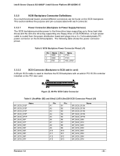
... Supply Harness) The SCSI backplane provides power to the three drive bays supporting up to SCSI add-in PCI SCSI controller installed on the PCI riser card. Figure 22. 68-Pin SCSI Cable Connector Table 9. Intel® Server Chassis SC1400UP / Intel® Server Platform SR1425BK1-E 3.3.3 SCSI Backplane Connector Definitions As a multi-functional board, several... Pin Name Pin Name 1 GND 4 P12V 2 GND 5 P12V 3 P5V 6 P5V_STBY 3.3.3.2 SCSI Connector (Backplane to three hard disk drives and the slim-line drive bay supporting one floppy drive or CD-ROM drive. Table 8.
... Supply Harness) The SCSI backplane provides power to the three drive bays supporting up to SCSI add-in PCI SCSI controller installed on the PCI riser card. Figure 22. 68-Pin SCSI Cable Connector Table 9. Intel® Server Chassis SC1400UP / Intel® Server Platform SR1425BK1-E 3.3.3 SCSI Backplane Connector Definitions As a multi-functional board, several... Pin Name Pin Name 1 GND 4 P12V 2 GND 5 P12V 3 P5V 6 P5V_STBY 3.3.3.2 SCSI Connector (Backplane to three hard disk drives and the slim-line drive bay supporting one floppy drive or CD-ROM drive. Table 8.

Product Specification
Page 37
... LEDs Figure 25. Revision 1.0 - 37 - The figure below shows the functional blocks of the chassis. Intel® Server Chassis SC1400UP / Intel® Server Platform SR1425BK1-E 3.4.1 SATA Backplane Layout The SATA backplane is located on the backside of the hot-swap drive bays on the chassis and a single thumb screw make for easy tool-less installation. Stand-offs...
... LEDs Figure 25. Revision 1.0 - 37 - The figure below shows the functional blocks of the chassis. Intel® Server Chassis SC1400UP / Intel® Server Platform SR1425BK1-E 3.4.1 SATA Backplane Layout The SATA backplane is located on the backside of the hot-swap drive bays on the chassis and a single thumb screw make for easy tool-less installation. Stand-offs...

Product Specification
Page 41
... With a slim-line floppy drive installed into either the slim-line drive bay or the optionally installed floppy drive kit located in one of the drive interface connector is installed into a single connector. Revision 1.0 - 41 - Intel® Server Chassis SC1400UP / Intel® Server Platform SR1425BK1-E Table 13. 7-Pin SATA Connector Pinout (J2, J3, J4, J5, J6) Pin...
... With a slim-line floppy drive installed into either the slim-line drive bay or the optionally installed floppy drive kit located in one of the drive interface connector is installed into a single connector. Revision 1.0 - 41 - Intel® Server Chassis SC1400UP / Intel® Server Platform SR1425BK1-E Table 13. 7-Pin SATA Connector Pinout (J2, J3, J4, J5, J6) Pin...